


Repair and Replacement
4–13
c. Line up the keyed (ridged) side of the cable-end with the notch in the GBIC.
d. Insert the cable-end into the GBIC until the cable-end is firmly seated.
e. Repeat steps a through d for the other end of the cable.
f. Verify the LED for the port displays a steady green. If a green light is not
displayed, try reinserting the GBIC into the switch element, and then reinsert the
cable end into the GBIC.
g. Repeat steps a through f for the remaining cables.
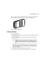
3. Place the ISL cables in the cable guide at the top of the SAN Integrated Switch for
organized cable management.
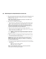
4. Connect the user fiber-optic cables to the user ports according to the switch and port
number indicated on the label, as appropriate to the fabric topology. For a listing of
user ports, as opposed to ISL ports, see Table 3–6, Page 3-18.
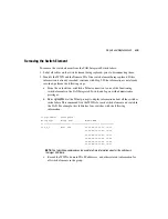
5. Enter the existing group information.
a. Log on to the new switch element with administrative privileges, using a Telnet
connection.
b. At the prompt, enter the
sgroupSet
command
.
c. Enter the requested information at the prompt.
d. Continue until all six switch elements are added to the group.
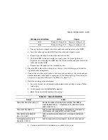
SAN Integrated Switch Model
Matrix
Diagram
IS/32
IS/64
Table 4–1: Group Information
Prompt
Action
Please Enter Group Type: [S64_6_1]
Indicates the number of user ports (case-sensitive). Press
Enter
to
accept the default S64_6_1. (If you have an IS/32 rather than IS/64, the
default will be S32_6_1.)
Please Enter Group Name: [ ]
Enter the name of the existing group. The group name cannot be null or
contain spaces, and can be up to 32 characters in length.
Enter member list by domain#?
(yes, y, no, n): [yes]
Enter y to specify members by domain ID, or n to specify members by
WWN.
For Group Member #1 enter its
Domain ID: (1..239) [0]
Enter the domain ID for switch element #1 (the far left switch element).