


1–4
SAN Switch Integrated/32 and Integrated/64 Installation and Hardware Guide
1–4
SAN Switch Integrated/32 and Integrated/64 Installation and Hardware Guide
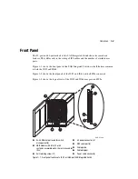
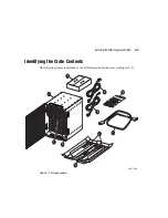
Figure 1–2: Front panels of the IS/32 and IS/64
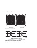
Figure 1–3: Logical view showing ISLs and user ports on the IS/32 and IS/64
For a list of available user ports, see Connecting the Fibre Channel Cables, page 3-18.
Front panel of IS/32
Front panel of IS/64
▼
indicates user port; interconnecting lines indicate ISLs
ISL cable configuration on IS/32
ISL cable configuration on IS/64
SHR-2195A
1
2
3
4
5
6
1
2
3
4
5
6
SHR-2196A