


4–6
SAN Switch Integrated/32 and Integrated/64 Installation and Hardware Guide
4–6
SAN Switch Integrated/32 and Integrated/64 Installation and Hardware Guide
3. If the switch element being replaced is partly or fully operational, back up the current
configuration. Refer to the section on Saving and Restoring the Switch Element
Configuration Settings, page 3-11.
NOTE:
Creating a backup copy of the switch element configuration is recommended for each
switch element in the SAN Integrated Switch.
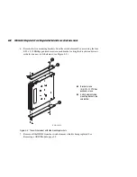
4. Disconnect the switch element being replaced.
a. Disconnect the power cable, first from the power source, then from the switch
element. Leave the cable in the power cable channel below the switch element.
NOTE:
The switch elements do not have an on/off button; they are powered up or down by
connecting or disconnecting the power cord. It is not necessary to power down the other switch
elements that were connected to the switch element being replaced.
b. If the serial cable is connected, disconnect it from the switch element.
c. Make sure both ends of each Ethernet cable are labeled with the switch element
number, then disconnect the Ethernet cable.
CAUTION:
The fiber-optic cables are fragile and should not be bent to a radius of less
than 0.5 inches.
d. Make sure both ends of each Fibre Channel cable are labeled with the port and
switch element number before disconnecting.
IMPORTANT:
Make sure the ISL cables are labeled and connected according to the cable
diagram in your SAN Integrated Switch (see
and
); otherwise, your
IS/32 or IS/64 will not operate correctly.
e. To disconnect each Fibre Channel connector from the port on the switch element
being replaced:
■
Firmly grasp the connector housing.
■
Pull the cable from the GBIC.
NOTE:
If you are only replacing one switch element, you need only disconnect the Fibre
Channel cables from that switch element being replaced.