


www.comdronic.co.uk
Fig. 4
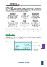
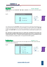
*The Design Flow for any automatic balancing valve will be achieved if the
Δp
across the valve reaches (or
exceeds) the design value.
If the Design
Δp
is met, the displayed message will be
FLOW OK
.
If the Design
Δp
is not met, the displayed message will be
LOW FLOW
.
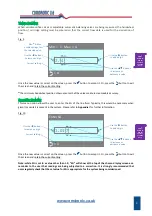
The DP Only Display (shown in fig. 5) is the simplest option available and may be preferred when the
AC6
is
being used as a simple manometer.
Fig. 5
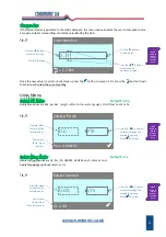
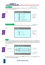
The Flow Only Display (shown in fig. 6) would normally only be the preferred display screen when fluid
velocities are being measured for the purposes of system flushing.
Fig. 6
7
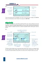
Up
arrow indicates
that the
Δp
must be
increased to achieve
the Design Flow.
Approx.
actual flow.
Design Flow for this
valve at this setting.
Δp
required to
achieve Design Flow.
Current valve
setting.
FlowCon Green Green.0 15‐25mm
LOW
FLOW
0.210
l / s
5.00
14.50 KPa
0.200
l / s
16.00
1.50
Down
arrow indicates
that the
Δp
is
unnecessarily high.
Measured
Δp
.
Difference between Measured
Δp
and Design
Δp
.
Flow status
message.*
Use the
▲
button to edit
the ‘Current Valve Setting’.
(
▲
not shown if valve is a fixed setting type).
Chevrons in the inlet
pipe indicate that the
flow is greater than zero.
Chevrons will show in
the outlet pipe when
Design Flow is achieved.
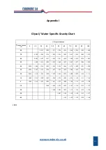
| KPa
4.27
Measured
Δp
.
Units of measure.
Kvs= 2.3 | m/s
1.37
Calculated Fluid
Velocity.
Units of measure.
16.1mm
Internal Pipe Diameter
being used to calculate
the fluid velocity.
Press
?
Button on
AC6 for
Context‐
Sensitive
Help.
Press
?
Button on
AC6 for
Context‐
Sensitive
Help.
Press
?
Button on
AC6 for
Context‐
Sensitive
Help.
Содержание AC6
Страница 2: ...www comdronic co uk ...
Страница 22: ...www comdronic co uk User Notes ...


