


www.comdronic.co.uk
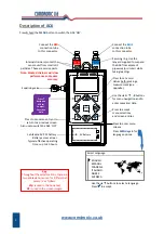
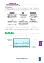
Fig. 2
*
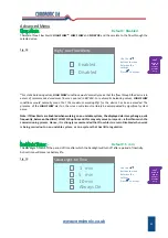
If the measured
Δp
reaches the design
Δp
for the selected valve, the flow status message will be
FLOW OK
.
However, if the design
Δp
is not met the flow status message will be
LOW FLOW
.
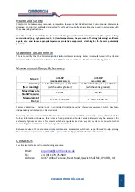
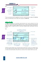
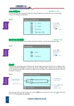
The Advanced Display can show more complex commissioning data and it may be preferred to the DP And
Flow Display if automatic balancing valves are being measured or if a system of proportional balancing is being
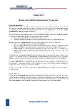
adopted. Fig. 3 shows an example of displayed data when a variable orifice valve has been selected and fig. 4
shows an example of displayed data when an externally adjustable automatic balancing valve has been
selected.
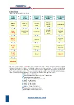
Fig. 3
**
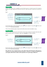
These are iterative processes due to the unknown valve authority in the circuit and so 2‐3 attempts may be
required to achieve the desired reading. Please also note that in conjunction with pressing the
◄
or
►
button
on the
AC6
, the physical handwheel setting of the valve will also need to be changed to match the new value.
6
Current cartridge
setting.
Flow status
message.
*
Details of the
selected valve.
Derived Flow.
Measured
Δp
.
20.48
FlowCon Green Green.0 15‐25mm
KPa
l / s
0.210
FLOW
OK
l / s
0.210
5.00
Design Flow for
this valve at this
setting.
Press the
▲
button to change
valve setting.
Current
handwheel setting.
Kvs of the selected
valve at the current
handwheel setting.
Derived Flow as a % of the
Target Flow. If no Target
Flow has been entered,
“‐‐‐“ is displayed.
Derived Flow.
Measured
Δp
.
5.30
Crane Variable D930/DM930 15mm
KPa
l / s
0.256
DESIGN
4.00 Kvs
4.00
101%
103%
TARGET
3.82
3.95
Press the
▲
button to MANUALLY
change the handwheel setting that
the
AC6
is using.
Derived Flow as a % of the
Design Flow. If no Design
Flow has been entered,
“‐‐‐“ is displayed.
Predictive handwheel
setting to achieve the
Design Flow.
Use the
◄
button to
AUTOMATICALLY
change the ‘Current
Handwheel Setting’
being used by the
AC6
to this value.
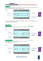
**
Predictive handwheel
setting to achieve the
Target Flow.
Use the
►
button to
AUTOMATICALLY
change the ‘Current
Handwheel Setting’
being used by the
AC6
to this value.
**
Press
?
Button on
AC6 for
Context‐
Sensitive
Help.
Press
?
Button on
AC6 for
Context‐
Sensitive
Help.
Содержание AC6
Страница 2: ...www comdronic co uk ...
Страница 22: ...www comdronic co uk User Notes ...


