


www.comdronic.co.uk
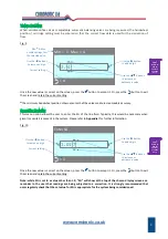
Damping Menu
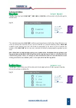
Default = 1.00
SEC
This screen allows the user to adjust the apparent sensitivity of the
AC6
by changing the time delay between
each screen update from a minimum value of 0.1
SEC
to a maximum value of 2.55
SEC
. A long Update Time may
be advisable on an unstable system in order to give a steadier reading.
Fig. 16
Once the new value is correct on the screen, press the
button to accept it. Or, press the button to exit
the screen and retain the current setting.
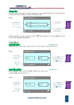
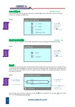
Default = 3.0
SEC
This screen allows the user to adjust the period of time over which readings are averaged, from a minimum
value of 0.6
SEC
to a maximum value of 11.0
SEC
. Increasing the Sample Time will make the screen appear to
update less frequently, but with a more stable reading.
Fig. 17
Once the new value is correct on the screen, press the
button to accept it. Or, press the button to exit
the screen and retain the current setting.
12
Update Time
2.00
SEC
Use the
▲▼
buttons for coarse
adjustment.
SAMPLE TIME
3.0 SEC
New Update Time.
Press
to accept.
Use the
◄
►
buttons for fine
adjustment.
Current Sample
Time is also shown
for information.
Sample Time
5.0
SEC
Use the
▲▼
buttons for coarse
adjustment.
New Sample Time.
Press
to accept.
Use the
◄►
buttons for fine
adjustment.
Press
?
Button on
AC6 for
Context‐
Sensitive
Help.
Press
?
Button on
AC6 for
Context‐
Sensitive
Help.
Содержание AC6
Страница 2: ...www comdronic co uk ...
Страница 22: ...www comdronic co uk User Notes ...


