


www.comdronic.co.uk
The
AC6
handset is supplied in a lightweight carrycase with the following accessories:
A removable rubber protector.
A pair of connection tubes, complete with manually‐operated isolation valves.
A pair of angle‐pattern Binder‐style connection adaptors with 3.3mm diameter needles.
A pair of straight‐pattern Binder‐style connection adaptors with 2.0mm diameter needles.
A set of hex keys (3mm, 4mm, 5mm, 6mm & 8mm) and a screwdriver.
A lanyard to suspend the handset from pipework whilst in use.
A strainer maintenance kit.
A spare battery.
Operating Instructions, a Quick‐Start Guide and a Factory Calibration Certificate.
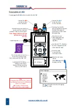
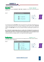
Connection Procedure
Note: each connection tube is fitted with an isolating valve and it is a matter of user‐preference whether
the tubes are used with the isolating valves adjacent to the
AC6
or, alternatively, adjacent to the subject
measuring valve / device.
1.
Select the correct connection adaptors for the valve / device being measured and attach them to
the connection tubes.
2.
Ensure that both isolating valves on the connection tubes are in the
CLOSED
position.
3.
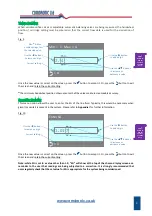
Attach the connection adaptor on the
RED
connection tube to the high‐pressure (upstream) test point
on the subject measuring valve / device.
4.
Attach the connection adaptor on the
BLUE
connection tube to the low‐pressure (downstream) test
point on the subject measuring valve / device.
5.
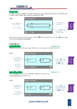
Ensure that the equalising valve on the
AC6
is
OPEN
.
6.
Attach the free ends of the
RED
and
BLUE
connection tubes to the colour‐coded connection points on
the
AC6
.
7.
OPEN
the isolating valves on the connection tubes to allow the line fluid to purge any air from inside
the tubes.
*
8.
CLOSE
the isolating valves on the connection tubes.
9.
Find a safe and static position for the
AC6
.
**
10.
Switch the
AC6
‘ON’ and press the
ZERO
button to set the datum at zero.
***
11.
OPEN
the isolating valves on the connection tubes and
CLOSE
the equalising valve on the
AC6
.
12.
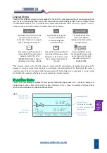
The
AC6
will now be reading
Δp
.
*
If the
Δp
across the valve / device is low, the purging process will be slow due to the internal resistance
of the
AC6
.
**
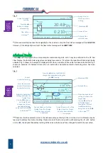
The
AC6
is very sensitive and readings will be affected if the position of the handset is moved or
adjusted after a datum has been set. A lanyard is provided and can be used to suspend the
AC6
from
adjacent pipework, as appropriate.
***
If the
AC6
is being subjected to an extreme change of temperature at this point, the datum may drift from
zero as the internal temperature of the meter changes and, in these circumstances, it will be necessary to
repeat this step until the internal temperature has stabilised and a zero datum is maintained.
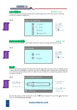
Disconnection Procedure
1.
OPEN
the equalising valve on the
AC6
.
2.
CLOSE
both isolating valves on the connection tubes.
3.
Disconnect the tubes from both the
AC6
and the valve / device.
3
Содержание AC6
Страница 2: ...www comdronic co uk ...
Страница 22: ...www comdronic co uk User Notes ...


