Columbia CEG-C Скачать руководство пользователя страница 5

5

VENTILATION & COMBUSTION AIR

!

WARNING

Air openings to combustion area must 

not be obstructed. Following instructions 

below, adequate combustion air can be 

maintained.

Provide combustion air and ventilation air in 

accordance with the section “Air for Combustion and 

Ventilation,” of the National Fuel Gas Code, ANSI 

Z223.1 / NFPA 54, or applicable provisions of local 

building codes. 
Provide make-up air where exhaust fans, clothes 

dryers, and kitchen ventilation equipment interfere 

with proper operation.
National Fuel Gas Code recognizes several methods 

of obtaining adequate ventilation and combustion air.  

Requirements of the authority having jurisdiction may 

override these methods.

• Engineered Installations.  Must be approved by 

authority having jurisdiction.

• Mechanical Air Supply.  Provide minimum of 

0.35 cfm per Mbh for all appliances located 

within space.  Additional requirements where 

exhaust fans installed.  Interlock each appliance 

to mechanical air supply system to prevent main 

burner operation when mechanical air supply 

system not operating.

• All Indoor Air.  Calculate minimum volume for all 

appliances in space.  Use a different method if 

minimum volume not available.

A.  Standard Method.  Cannot be used if known 

air in

fi

 ltration rate is 0.40 air changes per 

hour.  See Table 1 for space with boiler only.  

Use equation for multiple appliances.

Volume 

 50 ft

3

 x Total Input [Mbh]

B.  Known Air In

fi

 ltration Rate.  See Table 1 

for space with boiler only.  Use equation 

for multiple appliances.  Do not use an air 

in

fi

 ltration rate (ACH) greater than 0.60.

Volume 


21 ft

3

ACH x Total Input [Mbh]       

C.  Refer to National Fuel Gas Code for opening 

requirements between connected indoor 

spaces.

• All Outdoor Air.  Provide permanent opening(s) 

communicating directly or by ducts with outdoors.

A.  Two Permanent Opening Method.  Provide 

opening commencing within 12 inches of top 

and second opening commencing within 12 

inches of bottom of enclosure.


Direct communication with outdoors or 

communicating through vertical ducts. 

Provide minimum free area of 1 in² per 4 

Mbh of total input rating of all appliances 

in enclosure.


Communicating through horizontal ducts.  

Provide minimum free area of 1 in² per 2 

Mbh of total input rating of all appliances 

in enclosure.

B.  One Permanent Opening Method.  Provide 

opening commencing within 12 inches of top 

of enclosure.  Provide minimum clearance of 

1 inch on sides/back and 6 inches on front 

of boiler (does not supersede clearance to 

combustible materials).

C.  Refer to National Fuel Gas Code for additional 

requirements for louvers, grilles, screens and 

air ducts.

• Combination Indoor and Outdoor Air.  Refer 

to National Fuel Gas Code for application 

information.

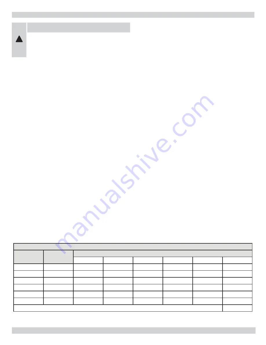
Table 1 - Minimum Room Volume, Indoor Air Only*

Input Mbh

Standard 

Method

Known Air In

fi

 ltration Rate Method (Air Changes Per Hour)

0.1

.02

.03

.04

.05

.06

112.5

5625

23625

11813

7875

5906

4725

3938

150

7500

31500

15750

10500

7875

6300

5250

187

9350

39270

19635

13090

9818

7854

6545

255

11250

47250

23625

15750

11813

9450

7875

262.5

13125

55125

27563

18375

13781

11025

9188

300

15000

63000

31500

21000

15750

12600

10500

* Table values based on boiler only. Add volume for any additional appliances.

Содержание CEG-C

Страница 1: ...P N 37411601 Rev B 05 2012 H CEG C GAS FIRED BOILERS FOR STEAM HEATING INSTALLATION OPERATION MAINTENANCE MANUAL COLUMBIA COMPANY Main offices and factory Pottstown PA ...

Страница 2: ...edure 4 Ventilation Combustion Air 5 Connecting Supply And Return Piping 6 Vent Installation 8 Vent System Modification 9 Vent Damper Installation 10 Connecting Gas Service 11 Electrical Wiring 12 Thermostat Installation 12 Wiring Diagrams And Component Coding 13 Lighting Instructions 16 Normal Sequence Of Operation 18 Connecting Supply And Return Piping Water Chilled Medium 19 General Instruction...

Страница 3: ...to the boiler room Modification substitution or elimination of factory equipped supplied or specified components may result in property damage personal injury or the loss of life To the owner Installation and service of this boiler must be performed by a qualified installer To the installer Leave all instructions with the boiler for future reference When this product is installed in the Commonweal...

Страница 4: ...fe lighting and other preference criteria with the gas manifold and control assembly provided on the boiler per the latest revision of ANSI Z21 13 This boiler shall be installed such that the gas ignition system components are protected from water dripping spraying rain etc during appliance operation and service circulator replacement condensate trap control replacement etc LOCATE BOILER on level ...

Страница 5: ...liances Do not use an air infiltration rate ACH greater than 0 60 Volume 21 ft3 ACH x Total Input Mbh C Refer to National Fuel Gas Code for opening requirements between connected indoor spaces All Outdoor Air Provide permanent opening s communicating directly or by ducts with outdoors A Two Permanent Opening Method Provide opening commencing within 12 inches of top and second opening commencing wi...

Страница 6: ...ions Refer to pages 21 22 for procedures on cleaning and skimming off impurities Near Boiler Piping is crucial for proper performance of a replacement steam boiler and should always be considered as part of the boiler installation Always be sure to include clean out and skimming tees in the near boiler piping These Tees are necessary for proper cleaning and servicing of the boiler For further pipi...

Страница 7: ...7 CONNECTING SUPPLY AND RETURN PIPING Figure 2 SUGGESTED PIPING FOR A MODULAR STEAM BOILERS Pumped Returns Figure 3 SUGGESTED PIPING FOR A MODULAR STEAM BOILERS Gravity Returns ...

Страница 8: ...rosion not less than that of galvanized sheet steel or aluminum not less than 0 016 inch thick No 28 GA Do not modify draft hood Connect flue pipe same as draft hood to chimney Bolt or screw joints together to avoid sag Flue pipe should not extend beyond inside wall of chimney Do not install manual damper in flue pipe or reduce size of flue outlet except as provided by the latest revision of ANSI ...

Страница 9: ... clothes dryers and any appliance not connected to the common venting system Turn on any exhaust fans such as range hoods and bathroom exhausts so they will operate at maximum speed Do not operate a summer exhaust fan Close fireplace damper Place in operation the appliance being inspected Follow the lighting instructions Adjust thermostat so appliance will operate continuously Test for spillage at...

Страница 10: ...Figure 6 Alternate Vent Damper Installation 7 Clearance of not less than 6 inches between Vent Damper and combustible construction must be maintained Additional clearance should be allowed for service of the Vent Damper 8 Vent Damper must be in open position when appliance main burners are operating 9 The Vent Damper position indicator must be in a visible location following installation 10 The th...

Страница 11: ...re 7 Gas line should be of adequate size to prevent undue pressure drop and never smaller than the pipe size of the main gas control valve Boiler and its gas connection must be leak tested before placing the boiler in operation To check for leaks in gas piping use a soap and water solution or other approved method WARNING Do not use an open flame Boiler and its individual shutoff valve must be dis...

Страница 12: ...ode ANSI NFPA No 70 and or local authority having jurisdiction THERMOSTAT INSTALLATION Thermostat should be installed on an inside wall at least two feet from a non insulated or outside wall approximately four feet above the floor NEVER install a thermostat on an outside wall Do not install a thermostat where it will be affected by A Drafts B Hot or cold pipes C Sun light D Lighting fixtures E Tel...

Страница 13: ...NG CAUTION Label all wires prior to disconnection when servicing controls Wiring errors can cause improper and dangerous operation Verify proper operation after servicing STEAM CONTROL AND INTERMITTENT IGNITION WIRING FOR PEG SERIES BOILER ...

Страница 14: ... MR PS MANUAL RESET PRESSURE SW SD STACK DAMPER CONTROL TERMINAL 1 K RELAY COIL 1 K1 RELAY CONTACTS 1 K2 RELAY CONTACTS LS LIMIT SWITCH MS MANUAL SWITCH CIR CIRCULATOR ECO ENERGY CUT OFF LWCO LOW WATER CUT OFF EWF ELECTRIC WATER FEEDER PG POWER GENERATOR PSC PILOT SAFETY COIL WIRE CONNECTION NOT ALL COMPONENTS LISTED ARE USED IN ALL CONTROL SYSTEMS WIRING LINE VOLTAGE BY FACTORY LOW VOLTAGE BY FAC...

Страница 15: ... K RELAY COIL 1 K1 RELAY CONTACTS 1 K2 RELAY CONTACTS LS LIMIT SWITCH MS MANUAL SWITCH CIR CIRCULATOR ECO ENERGY CUT OFF LWCO LOW WATER CUT OFF EWF ELECTRIC WATER FEEDER PG POWER GENERATOR PSC PILOT SAFETY COIL WIRE CONNECTION NOT ALL COMPONENTS LISTED ARE USED IN ALL CONTROL SYSTEMS WIRING LINE VOLTAGE BY FACTORY LOW VOLTAGE BY FACTORY LINE VOLTAGE BY INSTALLER LOW VOLTAGE BY INSTALLER NOTES 1 Sw...

Страница 16: ...n or turn by hand don t try to repair it call a qualified service technician Force or attempted repair may result in a fire or explosion Do not use this appliance if any part has been under water Immediately call a qualified service technician to inspect the appliance and to replace any part of the control system and gas control which has been under water OPERATING INSTRUCTIONS FOR INTERMITTENT PI...

Страница 17: ... call a qualified service technician to inspect the appliance and to replace any part of the control system and any gas control which has been under water 5 Turn gas control knob clockwise to off See Note 1 NOTE Some gas control knobs cannot be turned from pilot to off unless knob is pushed in slightly Do not force 6 Wait 5 minutes to clear out any gas If you smell gas stop Follow safety informati...

Страница 18: ...y restore the water or utilize an electric water feeding device which will automatically restore boiler water to its normal operating level Figure 10 Roll Out Safety Switch TO TURN OFF GAS TO APPLIANCE 1 Set thermostat to lowest setting 2 Turn off all electric power to appliance if service is to be performed 3 Remove access panel if present 4 Turn gas control knob clockwise to off NOTE Some gas co...

Страница 19: ...supplied with flow con trol valves or other automatic means to prevent gravity circulation of the boiler water during the cooling cycle 3 A hot water boiler installed above radiation level or as required by Authority having jurisdiction must be provided with a low water cutoff device either as a part of the boiler or at the time of boiler installation 4 Suggested piping for steam heating system ca...

Страница 20: ... it must be replaced If the safety valve leaks steam when the boiler is operating at normal pressures it should be immediately replaced Corrosion can build up rapidly at the valve seat and prevent its functioning as a safety device During the heating season the drain valve on the bottom rear of the boiler should be opened once a month to flush out the boiler so the device will be free to function ...

Страница 21: ...Check Safety Control Circuit after burner adjustments are made for satisfactory operation CAUTION Label all wires prior to disconnection when servicing controls Wiring errors can cause improper and dangerous operation Verify proper operation after servicing 1 Pilot with main burner operating turn the pilot gas adjusting screw clockwise until pilot gas is turned off See figures 8 and 9 on page 17 W...

Страница 22: ...ces of the compound out of the boiler Following blow down allow the boiler to cool Add fresh water slowly Be certain to blow enough times as required to remove compounds from system Checking And Adjusting The Gas Ignition Components The gas input to the boiler can be adjusted by removing the protective cap on the pressure regulator see figure 8 or 9 and turning screw clockwise to increase input an...

Страница 23: ...r and boiler room should not be restricted or blocked It is suggested that a qualified service agency be employed to make an annual inspection of the boiler vent system and low water cutoff including flushing of float types and heating system They are experienced in making the inspections outlined above and in the event repairs or corrections are necessary can make the proper changes for safe oper...

Страница 24: ...CEG112C 32425302 BASE PLATE CEG150C 32425303 BASE PLATE CEG187C CEG C REPLACEMENT PARTS BASE 32425304 BASE PLATE CEG225C 32425305 BASE PLATE CEG262C 32425306 BASE PLATE CEG300C 5 5612501 BASE WITH INSUL CEG112C 1 5612502 BASE WITH INSUL CEG150C 5612503 BASE WITH INSUL CEG187C 5612504 BASE WITH INSUL CEG225C 5612505 BASE WITH INSUL CEG262C 5612506 BASE WITH INSUL CEG300C 6 3342701 BURNER ASSY W PIL...

Страница 25: ...LUE COLLECTOR CEG150C 3442704 FLUE COLLECTOR CEG187C 3442705 FLUE COLLECTOR CEG225C 3442706 FLUE COLLECTOR CEG262C 3442707 FLUE COLLECTOR CEG300C 6 344 2 1 02 DRAFT HOOD CEG112C 1 344 2 1 03 DRAFT HOOD CEG150C 344 2 1 04 DRAFT HOOD CEG187C 344 2 1 05 DRAFT HOOD PEG225C 344 2 1 06 DRAFT HOOD PEG262C 344 2 1 07 DRAFT HOOD CEG300C 7 31423302 REAR PANEL CEG112C 1 31423303 REAR PANEL CEG150C 31423304 R...

Страница 26: ...05TIE ROD 1 4X19 CEG225 HW 011 07TIE ROD 1 4X23 CEG262 HW 011 08TIE ROD 1 4X25 CEG300 6 PF 007 02 PIPE FIT PLG 2 1 7 251 1 2 00 J BOLT 1 4 20X3 5 16 2 8 43300976 NIPPLE 2 MACH CEG112C 4 CEG150 6 CEG187 8 CEG 225 10 CEG262 12 CEG300 14 9 HW 016 02 DRAIN LONG 1 10 1570001 VALVE POP SAFETY 3 4 1 11 1150001 COUPLING 3 4 1 12 PF 005 10 PIPE FIT NPL 3 4 X 6 1 13HW 003 02 NUT 1 4 20 HEX SLT 4 14HW 008 01...

Страница 27: ... 24 1 WITH PROBE 4 HW 006 02 POP RIVIT FLUE 3 16 2 5 32421901 SENSOR BRACKET 1 6 AQ02101 CONTROL FIXED TEMP 2 ONE ON DRAFT HOOD 7 37513301 WIRE ROLL OUT 1 8 HW06501 SCR 6X1 4 SLOT 2 9 753 1 3 00 90 SYPHON 1 10 PF 025 01 1 4 TEE 1 11 PF 026 05 1 4 X 3 NIPPLE 1 12 GA 003 00 PRESSURE GAUGE 1 13 PF 027 01 1 4 ELBOW 90 1 14 SS 001 01 PRESSURE SWITCH 1 15 PF 026 01 CLOSE NIPPLE 1 4 NPL 1 16 PF05601 PIPE...

Страница 28: ... TO J BOX 18 1 4 PB00702 IGN WIRE 30 CIDE MODELS ONLY 1 5 37413602 HARNESS IGN MOD TO GAS VALVE 12 1 6 PB00604 SPK CTL S8600M1013 1 7 37413201 WIRE SPILL SWITCH 47 1 8 37413801 WIRE J BOX TO CONTROLS 27 1 9 EF03601 WIRE CLAMP 3600 WHITE 1 10 37413002 WIRE TRANSFORMER WHITE 15 1 11 37413001 WIRE TRANSFORMER BROWN 15 1 12 3641601 TRANSFORMER ASSEMBLY 24V 1 13 37413101 DAMPER CABLE 53 1 14 3641501 EL...

Страница 29: ...put by 240 STANDARD EQUIPMENT Crafted Boiler Drafthood Low Water Cut off Probe Type Deluxe Jacket Wiring Automatic Vent Damper Ported Stainless Steel Burners Blocked Vent and Roll Out Safety Switches Gas Valve Pilot Pressure High Limit Control 2 2 Supply Tapping L H Plugged 2 2 Return Tappings L H Plugged Packed in Separate Carton Pop Safety Valve and Boiler Drain OPTIONAL EQUIPMENT Electronic wat...

Страница 30: ...30 INSTALLATION NOTES ...

Страница 31: ...31 INSTALLATION NOTES ...

Страница 32: ...COLUMBIA COMPANY Main offices and factory Pottstown PA ...

Отзывы: