Columbia Weather Systems, Inc.
25
Attaching the Wind Sensors to the Cross Arm Support
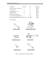
Refer to Figure 3 as the individual wind sensors are assembled to the cross arm
support.
Set the wind speed and direction sensor bodies onto their respective ends of the
cross arm support. Each sensor body is marked with either an "I” or “II” and should
be matched to the same mark on either end of the cross arm support.
Line up the marked hole in each sensor body with the correspondingly marked holes
(1/8" diameter) at either end of the cross arm support.
Using a Phillips screwdriver, screw the stainless steel sheet metal screws from the
Hardware Kit through the predrilled holes and directly into the pilot holes in the cross
arm support.
Assemble the U-bolt Assembly onto the Cross Arm Support. Refer to Figure 3 for
the proper order of assembly. Thread the two nuts onto the ends of the U-bolt arms
so that the ends of the arms are flush with the outside faces of the nuts. (The nuts
will be tightened later after the mast is inserted through the U-bolt assembly.)
Pre-Calibrating the Wind Direction Sensor
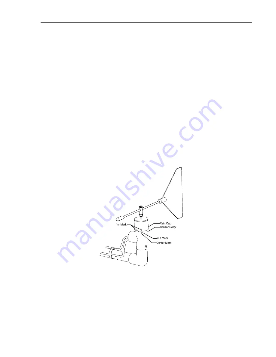
Figure 9: Marking the Wind Direction Sensor
With the wind sensor cable still connected to the console back panel, hold the
sensor body vertical so the vane rotates in a horizontal plane. Then rotate the vane
and the rain cap on the wind direction assembly clockwise (when viewed from
above); stop as soon as the NNE light on the front panel is illuminated. Mark the
position of the rain cap to the sensor body with a pencil by marking a vertical line
that extends from the rain cap down onto the sensor body.
Содержание CAPRICORN II PLUS
Страница 2: ...2 Capricorn II Plus User Manual...
Страница 4: ...4 Capricorn II Plus User Manual...
Страница 6: ...6 Capricorn II Plus User Manual...
Страница 32: ...32 Capricorn II Plus User Manual...
Страница 36: ...36 Capricorn II Plus User Manual...
Страница 54: ...54 Capricorn II Plus User Manual...


