background image

Columbia Weather Systems, Inc.

41

1.

In the “Silent” mode, only the LED light(s) corresponding to the sensor that is
set, either “Temperature” or “Speed” or both, will illuminate upon detection of
the set condition. The LEDs will remain lit until the condition ceases or the
Alarm switch is moved to the “Off” position.

2.

In the “Audible” mode, in addition to the visible LED alarm, a speaker mounted
inside the back panel will sound an audible alarm upon detection of a set
condition. The audible alarm may be disabled by moving the Alarm switch to
the “Off” position. Simply moving the switch to the “Silent” position will not
disable the audible alarm unless the alarm condition has ceased to exist (LED
is no longer lit).

3.

A sudden power interruption (drop, loss or surge) may also cause the alarm to
activate. If this occurs, the audible alarm can be disabled by moving the alarm
switch to the “Off” position. (It is also possible that the system microprocessor
has not been properly reset. To insure proper reset, unplug and then replug the
console power cord from the wall receptacle.)

Setting The Temperature Alarm

Two temperature scales are available to set the temperature alarm. The scale on the
right is for setting the alarm to be activated when detecting temperatures below the
freezing point of water, and the one on the left is for temperatures at or above the
freezing point. The scale selector switch, below the Alarm switch and to the left of
the Temperature scales, is used to select the desired scale.

Note: Only when a sensor is attached to the temperature terminals on the back
panel will activate the alarm feature.

1.

First, move the Alarm switch on the front panel of the console to the “Off”
(reset) position to reset the feature.

2.

After the temperature/wind alarm values are set, move the switch to either the
“Silent” or “Audible” position, as desired, to set the alarm.

3.

To set the alarm to activate when the temperature rises above a certain point,
move the Temperature Alarm switch on the back panel of the console to “when
rising.”

4.

To activate the alarm when the temperature drops below a certain point, move
the Temperature Alarm switch to “when falling.”

For example, if you wanted the alarm to activate when the outdoor tempera-
ture falls to 32

o

 F, you would:

a.

move the Alarm switch on the front panel to the “Off” position;

b.

move the Temperature scale selector switch to the up position;

c.

move the Temperature slide switch to the bottom setting (32

o

 F);

d.

move the Temperature Alarm switch on the back panel to the “when

falling” position; and

Содержание CAPRICORN II PLUS

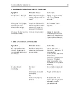
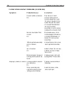
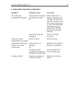
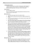
Страница 1: ...ice Printed in U S A Copyright 1998 Columbia Weather Systems Inc All Rights Reserved Proprietary Notice Capricorn II Plus is a trademark of Columbia Weather Systems Inc The information and drawings co...

Страница 2: ...2 Capricorn II Plus User Manual...

Страница 3: ...duct It is a precision instrument however and requires proper installation and a certain amount of regu lar maintenance The Capricorn II Plus is quite easy to install and you may be tempted to skip th...

Страница 4: ...4 Capricorn II Plus User Manual...

Страница 5: ...ATHER until the following steps are completed Failure to follow this request will jeopardize your claim 1 Open the container and inspect the contents Do not throw away the container or any damaged par...

Страница 6: ...6 Capricorn II Plus User Manual...

Страница 7: ...Mounting 30 B Wall Mounting 31 SECTION 5 CALIBRATION 34 A Calibrating the Temperature Sensors 34 B Calibrating the Humidity Sensor 34 C Calibrating the Barometric Pressure Sensor 35 D Calibrating the...

Страница 8: ...ed Display Problems 50 F Wind Speed Display Problems Continued 51 G Wind Direction Display problems 52 H Wind Sensor Tests 53 SECTION 9 REPLACEMENT PARTS 56 SECTION 10 USER SUPPORT INFORMATION 58 A Li...

Страница 9: ...d the highest wind speeds A battery backup feature assures that these readings will not be forgotten if power is either interrupted or cut off entirely An alarm feature provides an audible and visible...

Страница 10: ...sed skin as a given combination of wind and temperature Please refer to Addendum Wind Chill Algorithm Display Replaces normal temperature display via a front panel slide switch Range 99o F to 91o F 99...

Страница 11: ...te Computed over a 0 5 second period and output to the display every 0 5 second Electronic Display Resolution 1 mph Mechanical Threshold Speed Responds to winds of 0 5 mph Memory Mode Two wind speed v...

Страница 12: ...four seconds and continues until the springloaded slide switch is reset to either a clear the memory or b return to current condition display Alarm Controlled Output Feature The maximum control signa...

Страница 13: ...es in light oak or dark walnut Section 7 Maintenance includes instructions on how to keep the cabinet looking new Front Panel Figure 1 Front Panel Capricorn II Plus Console Temperature Humidity Indica...

Страница 14: ...ctors Temperature Humidity Display Switch Temperature Alarm Switch Humidity Sensor Cable Connectors Temperature Sensor Cable Connectors 12V Relay Connector Alarm Controlled Output RS232C Interface Con...

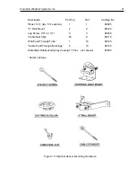
Страница 15: ...6 5 U BOLT ASSEMBLY PLATED STEEL SHEET METAL SCREW FOR CROSS ARM SUPPORT STAINLESS STEEL QTY 2 TOP SCREW FOR DIRECTION VANE STAINLESS STEEL TOP LOCK NUT FOR WIND SPEED SENSOR STAINLESS STEEL INTERNAL...

Страница 16: ...g with two cables protruding which in turn is con nected by a single cable to a wind speed sensor body 4b white T shaped PVC fitting 1 50 foot wind sensor cable coil with connector half 1 Hardware Ass...

Страница 17: ...l Materials Needed See also Section 4 Optional Sensor Mounting Hardware Black PVC Electrical Tape 2 4 Plastic Wall Bushings Mast Height above structure Minimum 5 ft recommended 10 ft Taller may be pre...

Страница 18: ...cover and firmly pull the circuit board out of the fuse compartment Reinsert the board with the desired line voltage range as indicated on the back panel Close the fuse cover and insert the power cor...

Страница 19: ...ys light properly When power is first ap plied the display digits may not come on or the values may be incorrect This is normal If the display does not light up within 30 seconds unplug the unit wait...

Страница 20: ...by splicing on the extra length of 22 gauge stranded 2 conductor shielded cable with a ground drain wire When cutting and splicing insure good contacts proper color coding of the terminal leads and a...

Страница 21: ...ion shielded from direct or reflected sunlight Mounting the sensor under roof eaves is appropriate in most applications Avoid locations where ice and snow will accumulate or near heat radiating object...

Страница 22: ...t provided in the 1 2 EMT elbow conduit The relative humidity sensor is supplied with a standard 25 foot cable The cable provided is a 22 gauge 2 conductor shielded cable with a ground drain lead If a...

Страница 23: ...be caused by accidental shock to the shaft Place the wind cup hub assembly on the threaded shaft of the wind speed sensor so that the cup assembly rests on and mates to the inverted shaft nut which h...

Страница 24: ...shaft of the wind direction sensor body so that the washer sits on the inverted nut Note The wind direction sensor body has two cables attached to it Place a 3 8 wrench on the inverted nut Holding the...

Страница 25: ...in the cross arm support Assemble the U bolt Assembly onto the Cross Arm Support Refer to Figure 3 for the proper order of assembly Thread the two nuts onto the ends of the U bolt arms so that the en...

Страница 26: ...thods for mounting the mast to a roof or building structure Sloped roof mounting flat roof mounting or wall mounting See Section 4 Optional Sensor Mounting Hardware for more information Location Do no...

Страница 27: ...rrated edge of the U bolt clamp Tighten the two nuts on the U bolt assembly so that the Wind Sensor Assembly is lightly fastened to the mast Final adjustment and tightening are described below With th...

Страница 28: ...od solder splice and water proof insulation are essential merely twisting the respective wires together is not adequate Additional cable Cat No 81540 and a water tight splice kit Cat No 81580 are avai...

Страница 29: ...Mast Mount1 4 3 88030 1 4 x 2 1 4 for comp roofs SECTION 4 OPTIONAL SENSOR MOUNTING HARDWARE A complete Wind Sensor Mounting Hardware Kit is available for roof mounting Cat No 88002 or wall mounting...

Страница 30: ...090 Turnbuckles 6 open x 4 closed 2 not shown 88100 Cable Nail Clips 20 8 88110 Wall Feed Through Tube1 1 10 88130 Cable Feed Through Bushings1 4 10 88140 Watertight Rubberized Spray 17 75oz not shown...

Страница 31: ...kg Ref Catalog No Mast 10 ft two 5 ft sections 1 1 88005 4 Wall Mount 2 9 88120 Lag Screw 1 4 x 2 1 4 4 3 88030 Cable Nail Clips 20 8 88110 Wall Feed Through Tube1 1 10 88130 Cable Feed Through Bushin...

Страница 32: ...32 Capricorn II Plus User Manual...

Страница 33: ...er Use an insulated container for best results A Thermos type container is preferable Allow the temperature throughout the ice bath to stabilize by waiting five minutes before proceeding 5 Place the t...

Страница 34: ...stable and steady barometric pressure conditions 10 feet in height equals 0 01 in Hg 3 meters in height equals approximately 0 33 mbar With these considerations in mind calibrate the barometric pressu...

Страница 35: ...o coarse screw clockwise until lowest value is displayed Then slowly turn the screw counter clockwise until the display is near the calibrate value see Step 2 Make the final adjustment by turning the...

Страница 36: ...36 Capricorn II Plus User Manual...

Страница 37: ...ition Note When the unit is in the calibrate mode the averaging will not be per formed and the memory will not be updated with high low temperature values The temperature display may appear unstable a...

Страница 38: ...h digit in the Barometric Pressure display has varying levels of importance For example 29 96 in Hg would read Digit Number 1 2 3 4 Sample Reading 2 9 9 6 Digit 1 is significant but relatively unchang...

Страница 39: ...and television are frequently several hours old it is likely that the Capricorn II Plus will not agree with the broadcast readings during changing weather conditions Additionally the Capri corn II Pl...

Страница 40: ...in 11 25o or better The illuminated compass point indicates the direction the wind is coming from For example when the unlabeled light between N and NE is illuminated the wind is blowing from or out o...

Страница 41: ...scale on the right is for setting the alarm to be activated when detecting temperatures below the freezing point of water and the one on the left is for temperatures at or above the freezing point The...

Страница 42: ...red wind speed alarm as described above move the temperature scale switch below the alarm switch to the down position move the Temperature slide switch down to 30o F and move the Temperature Alarm swi...

Страница 43: ...ollowing table shows the status of the alarm functions under different condi tions h c t i w S s g n i t t e S r o t a c i d n I D E L s t h g i L y a l p s i D D E L s t i g i D r e k a e p S y a l e...

Страница 44: ...he Memory switch to the Erase position The Capricorn II Plus will immediately purge the previously stored high low readings and begin storing new information 3 Current Display Move the switch to the O...

Страница 45: ...rs may be defective Refer to Section 8 Troubleshoot ing and call the factory for service as required B BAROMETRIC PRESSURE SENSOR MAINTENANCE The barometric pressure sensor is located inside the cabin...

Страница 46: ...ed service This can be tested by spinning the sensors They should spin freely If they do not call the factory for service All or part of the wind sensors may need to be replaced Since the circuit is m...

Страница 47: ...c i t a r r E n o d e n r u t t s u j t i n U s d e e n r o s s e c o r p o r c i m e t a l u c l a c o t e m i t e g n a h c d n a s e g a r e v a y a l p s i d r O r o f s d n o c e s l a r e v e s...

Страница 48: ...o r P e l o s n o c o t s e r i w r o s n e s e r u t a r e p m e T e v i t c e f e d r o s n e s e c a l p e R y l b m e s s a k n a l b s i y a l p s i D e v i t c a n i r e t u p m o c o r c i M n...

Страница 49: ...S d r o c r e w o p d n u o r G h t r a E g n i n t h g i L m o t p m y S e s u a C e l b a b o r P n o i t c e r r o C t u b d n i w t n e r a p p a o N 0 n a h t r e h g i h r e b m u n n o d e h s...

Страница 50: ...e r u t c a f u n a m t l u s n o c r o s n e s w e n r o f r e l a e d y l b m e s s a y l b m e s s a b u h p u c d n i W n e k o r b s i m r a r O w e n a r o f y r o t c a f t c a t n o C y l b m...

Страница 51: ...s e t m r o f e P g n i w o l l o f r o t c e n n o c e l b a c d n i W d e g g u l p n u e l b a c d n i w n i g u l P r o t c e n n o c t h g i l t o n o d s t h g i L d e t a t o r s i s a y l l a...

Страница 52: ...splay of any number other than 0 should appear as the white terminal is being tapped If that is the case the console is functioning properly Check the entire length of the cable for any cuts kinks or...

Страница 53: ...be returned for repair Unplug the wind sensors from the main cable Do not send the cup hub assembly or the wind vane as they may be damaged in shipping 3 If any or all of the direction lights do not...

Страница 54: ...54 Capricorn II Plus User Manual...

Страница 55: ...81420 with top screw Temperature Probe Assembly 81520 Includes one complete sensor Assembly with 25 ft cable Humidity Proble Assembly 81525 Includes one complete sensor with 25 ft calbe Hardware Assem...

Страница 56: ...Option 81585 Allows quick disconnect of cables from temperature sensor watertight Factory installed Sensor Cable Connector Option 81590 Allows quick disconnect of cables from humidity sensor watertigh...

Страница 57: ...om date of purchase subject to the provisions contained herein CWS warranty shall extend to the original purchaser only and shall be limited to factory repair or replacement of defective parts EXCLUSI...

Страница 58: ...provide the current replacement value of the item being shipped for insurance purposes d Send to Capricorn Service Dept Columbia Weather Systems 2240 NE Griffin Oaks Street Suite 100 Hillsboro Oregon...

Страница 59: ...35 4 133 25 30 5 123 33 25 6 110 41 20 7 87 74 15 8 61 82 10 9 14 152 5 10 0 0 5 CF Table 1 Table 2 1 16 Remainder Wind Speed 5 Then compute the WIND CHILL WC use the following formula IF temperature...

Отзывы: