Page
31
of
47
NEPTUNE HQ
The Step Calibration result image is shown as below:
Fig 41: The Step Calibration Parameters
First, feed the Base Step Value as 128000 (this is the approximate value and this need to be corrected by
following the below steps).
Follow these steps to perform step calibration:
Step 1:
Select the desired pass from the list and click on the
button (Refer to Fig 40).
Step 2:
Feed the correction value in the
Revise
field (the correction value up to two decimal places) (Refer
to Fig 41).
Step 3:
Click on the
=>
icon (Refer to Fig 41) on the Step Calibration window. The correction value result
will be reflected in the
Step
field (Refer to Fig 41). The same step value will also be displayed in the
Steps
field on the
Quick Access Toolbar
.
Mechanical Checks
Accurate mechanical alignment is the key for achieving good print quality. In case of misalignment, the
Print Heads have to be adjusted manually using the provided tools and alignment should be re-verified
iteratively until the Print Heads are perfectly aligned.
Angle Check
This test checks the mounting angle of all the Print Heads. Print Heads should be mounted at exactly 90
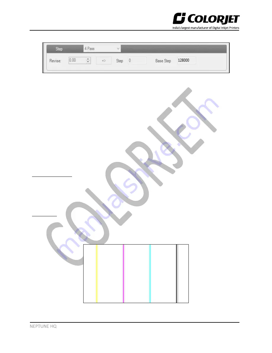
degrees to the carriage scan direction. In the figure below, when the Print Heads are mounted correctly
at 90 degrees, then an unbroken vertical straight line pattern is formed, as shown below:
Fig 42: The Good Quality Angle Test


