TABLE OF CONTENTS
SAFETY GUIDELINES
----------------------------------------------------------------------------------------------3
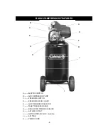
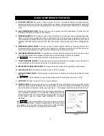
BASIC COMPRESSOR FEATURES
---------------------------------------------------------------------------4
ELECTRIC MOTOR-----------------------------------------------------------------------------------------------------5
AIR COMPRESSOR PUMP-------------------------------------------------------------------------------------------5
PRESSURE SWITCH --------------------------------------------------------------------------------------------------5
PRESSURE RELIEF VALVE------------------------------------------------------------------------------------------5
AIR PRESSURE REGULATOR--------------------------------------------------------------------------------------5
TANK PRESSURE GAUGE-------------------------------------------------------------------------------------------5
REGULATED PRESSURE GAUGE---------------------------------------------------------------------------------5
AIR LINE OUTLET-------------------------------------------------------------------------------------------------------5
AIR TANK DRAIN VALVE----------------------------------------------------------------------------------------------5
AIR TANK------------------------------------------------------------------------------------------------------------------5
POWER CORD-----------------------------------------------------------------------------------------------------------5
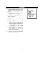
ASSEMBLY
--------------------------------------------------------------------------------------------------------------6
OPERATION
------------------------------------------------------------------------------------------------------------7
PRIMING
THE PUMP------------------------------------------------------------------------------------------------7
STARTUP------------------------------------------------------------------------------------------------------------------7
SHUTDOWN--------------------------------------------------------------------------------------------------------------7
MAINTENANCE CHART
--------------------------------------------------------------------------------------------8
TROUBLESHOOTING CHART
-----------------------------------------------------------------------------------9
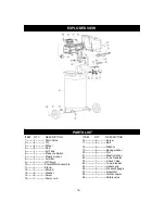
PARTS DRAWING&PRATS LIST
-------------------------------------------------------------------------------10
WARRANTY-------------------------------------------------------------------------------------------------11
SPECIFICATION
ITEM NO. --------------------------------------CM 01213-15
PUMP-------------------------------------------OIL LUBE DIRECT DRIVE
MOTOR-----------------------------------------2.5 Continuous HP
VOLTAGE/AMPS/PHASE------------------120/15/1
AIR TANK CAPACITY-----------------------15 GALLON
CUT-IN PRESSURE-------------------------95 PSI
CUT-OUT PRESSURE---------------------125 PSI
CFM @ 40 PSI--------------------------------5.0
CFM @ 90 PSI--------------------------------4.0
POWER CORD-------------------------------STW 14 AWG / 72” LENGTH
NOTE
: Avoid use of extension cords. If cannot be avoided, the cord should be a minimum
wire size of 12 AWG and no longer than 50 feet.
Use only a 3-wire extension cord that has a 3-blade grounding plug, and a 3-slot
receptacle that will accept the plug on the product.
- 2-

