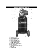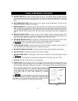
BASIC COMPRESSOR FEATURES
A. ELECTRIC
MOTOR:
The motor is used to power the pump. It contains a thermal overload protector
and an automatic reset. If the motor overheats for any reason, the thermal overload protector will shut it
down to prevent the motor from being damaged. The motor will automatically restart when it completely
cools.
B. AIR
COMPRESSOR
PUMP:
The pump is used to compress the air and discharge it into the tank via
the piston moving up and down in the cylinder.
C. PRESSURE
SWITCH:
The switch is used to start or stop the air compressor and is operated manually.
When in ON position, it allows the motor to start when the air tank pressure is below the factory set
cut-in pressure and allows the motor to stop when the air tank pressure reaches the factory set cut-out
pressure. ALWAYS set this switch to OFF when the unit is not being used, and before unplugging the
unit.
D. PRESSURE
RELIEF
VALVE:
The valve is used to prevent system failures by relieving pressure from
the system. When the pressure reaches the preset level, the pressure switch will not shut down the
motor. It will automatically pop open or you can pull the ring on the valve to open.
E. AIR
PRESSURE
REGULATOR:
The regulator is used to adjust line pressure to the tool you are using.
Turn the knob clockwise to increase pressure and counterclockwise to decrease pressure.
WARNING
:
Never exceed the maximum working pressure of the tool.
F. TANK PRESSURE GAUGE:
The gauge is used to measure the stored air pressure level of the tank. It
is not adjustable by the operator, and does not indicate line pressure.
G. REGULATED
PRESSURE
GAUGE:
The gauge is used to measure the regulated outlet pressure.
H. AIR
LINE
OUTLET:
The outlet is used to connect 1/4” NPT air hose.
I.
AIR TANK DRAIN VALVE:
The drain valve is used to remove moisture from the air tank after the unit is
shut off.
WARNING
:
Never attempt to open the drain valve when the tank pressure is over 10 PSI.
J. AIR
TANK:
The tank is used to store the compressed air.
K. POWER
CORD:
This product is for use on a nominal 120 volt circuit and should be grounded. A cord
with a grounding plug as illustrated must be used. Make sure that the product is connected to an outlet
having the same configuration as the plug (see Figure 1). No adapter should be used with this product.
Check with a licensed electrician if the grounding instructions are
not completely understood, or if in doubt as to whether the product
is properly grounded. Do not modify the plug provided. If it will not
fit the outlet, have the proper outlet installed by a licensed
electrician.
DANGER
:
Improper installation of the grounding plug will result
in a risk of electric shock. If repair or replacement of the cord or plug
is necessary, do not connect the grounding wire to either flat blade
terminal. The grounding wire is in the green outer surface.
Grounded
outlet
120V/15 A
Grounding Pin
Plug
- 5-
Figure1

