


III.
PRE-STARTUP
1.
STARTUP CHECKLIST - Review and use. (Typically located at end of this manual.)
2.
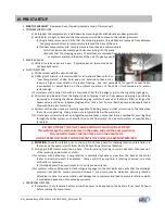
COMPRESSOR MOUNTS
a)
As shipped, the compressor(s) is held down by mounting bolts with vibration rubber grommets.
b)
Verify bolts are tight to base and that the compressor is able to move on the rubber grommets.
(1)
Single Compressor units: Verify that the shipping spacers (if installed) are removed from between
the compressor bottom (or compressor plate) and the base of the unit.
(2)
Tandem Compressor units: Compressors are mounted on a common plate.
(a)
Do not loosen the compressor bolts connecting it to the plate.
(b)
Verify that the shipping spacers (if installed) are removed from between the compressor (or
compressor plate) and the base of the unit. (Typically quantity of 6).
3.
SERVICE VALVES
a)
Verify all service valves are open. (Typical valves on these models do
not have backseats.)
4.
FLUID IN SYSTEM:
a)
Fill the system with the desired solution.
b)
A 30% glycol mixture is recommended for all standard flow units. For
“Low Temperature” chilled fluid and units installed outdoors may
require a higher concentration to prevent freezing. See unit nameplate for specific concentration
requirements or adjust based on the ambient conditions of the chiller, fluid temperature, and/or
system design.
c)
For systems with a tank, fill to within a few inches from the top edge or just to the top of the sight glass.
d)
Fill system and bleed air from the highest point of piping. Vent air from pump and piping is possible by
loosening or removing the strainer blowdown plug, which will vent air as the tank is filled, as long as the
bypass valve is still open. Replace plug/cap after tank is full. Ensure that the pump and evaporator are
filled with fluid prior to starting.
e)
Systems with an open tank are typically capable of bleeding excess air that is returned to the tank when
the system is operating. Piping in and out are typically below the water line.
f)
For stationary systems (without an integral pump and tank), ensure that there is method for ensuring flow
through the chiller system, such as with the use of a flow switch. See electrical system or specifications
for details.
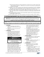
g)
ROTATION: Check for rotation prior to start-up. Do not use pump for checking rotation unless fluid is in
the tank and the pump is full of fluid. Verify 3-Phase Power Electrical Rotation:
h)
All 3-phase (3Ø) motors are wired in phase. If motors are not turning in correct direction, then reverse 2
of the incoming power wires to chiller.
i)
For systems with 3Ø pumps: Pump rotation is normally clockwise as view from the back of the motor
(Refer to direction decals if available). Pumps will still pump fluid if rotating reversed, so actual
verification is necessary.
(1)
Quickly depress the pump contactor to verify proper rotation.
j)
For systems without 3Ø pumps: Attach refrigerant gauges to the test ports and verify that the discharge
pressure rises and the suction pressure decreases. Loud noise may be indication of wrong rotation.
Extended run time in reverse rotation will damage the compressor and lead to premature failure which
is considered abuse and not covered by warranty.
5.
CRANKCASE HEATERS:
a)
If compressor has crankcase heaters, allow the power to be applied to the heaters for at least 24 hours
before starting the compressor.
DO NOT ATTEMPT TO START CHILLER WITHOUT FLUID IN THE SYSTEM!!
This will damage the mechanical seal in the pump and void the pump warranty.
Also, potential freeze condition may exist in the evaporator.
DO NOT RESET ANY SAFETY CONTROLS UNTIL THE CAUSE HAS BEEN DETERMINED.
MNL_Standard-Basic_ACWC-24to240-E-(IN PROGRESS)_(0815).docx
- 8 -
Содержание ACWC-180-EM-DR-LT-0-5
Страница 35: ...Notes...
Страница 36: ...MAINTENANCE RECORD DATE PROCEDURE PERFORMED...


