Marrone & Co., Inc.
2730 Maximilian Drive • Houston, Texas 77032 • Phone (281) 227-8400 • (800) 473-9178
Fax (281) 227-8404 • www.waterchillers.com
Guide_DeltaPLC-ProgramOperations-A1_020816.docx
DELTA TEMPERATURE CONTROLLER OPERATIONS
A1 Model
OPERATION
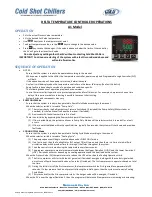
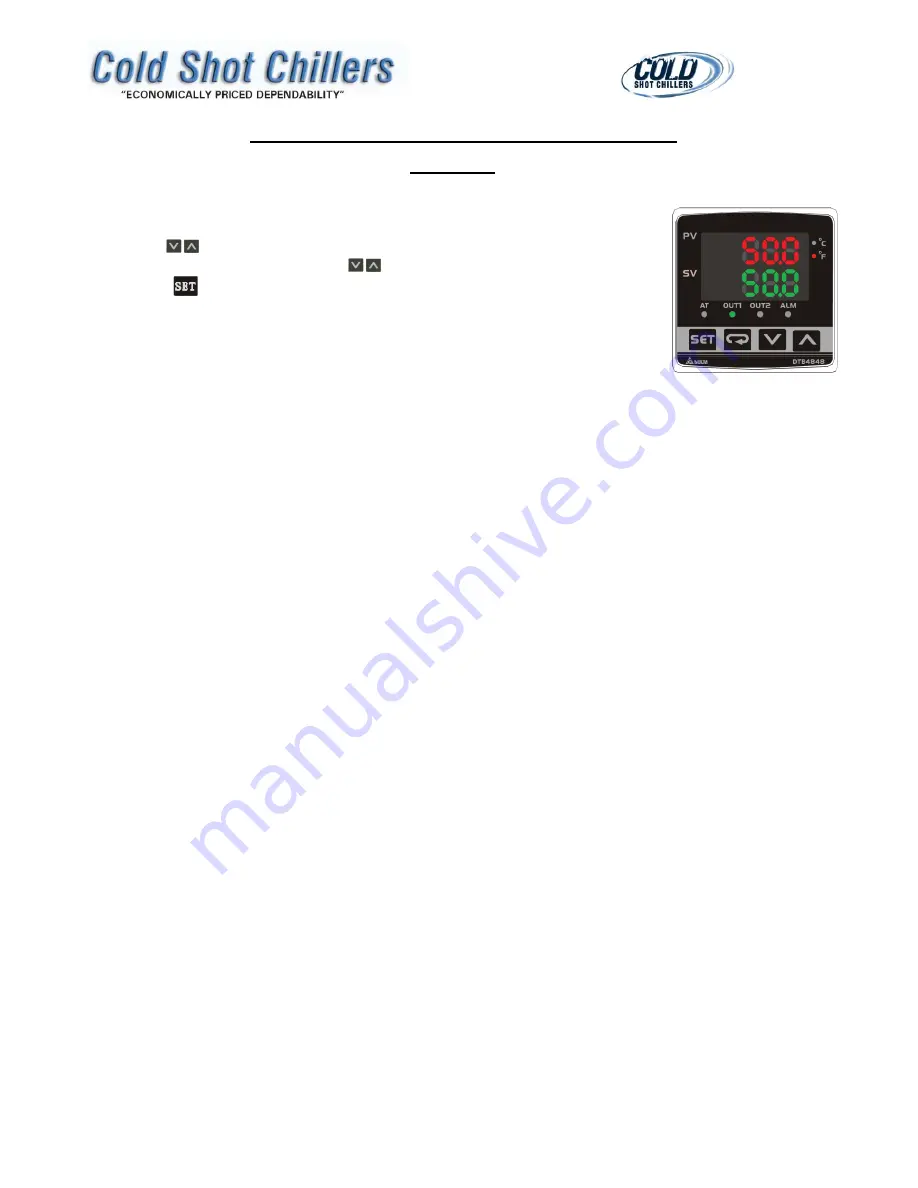
PV is the actual Process Value temperature.
SV is the desired Set Value temperature.
Use
keys to set the temperature set point.
To adjust temperature value, use the
keys to change to the desired value.
Press
key to save the changes. If the value is above or below the limits of the controller,
the SV will go to the closest limit value.
Do not adjust any settings other that SV without contacting Cold Shot Chillers.
IMPORTANT! Continuous restarting of the system with a fault is considered abuse and
will void all warranties.
SEQUENCE OF OPERATION
NOTES:
-
Ensure that the system is ready to be operated according to the manual.
-
When power is applied to the chiller, the temperature controller, power supply and Programmable Logic Controller (PLC)
will be lit.
-
If the above items do not have power at start up, determine cause.
-
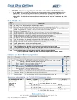
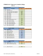
Any faults will be displayed on the temperature controller on the lower SV display. (See Fault Code List)
-
Some faults are dependent on mode of operation and condition specific.
-
The following sequence of operation provides basic overview.
-
Control timers may limit operations to protect equipment and for efficiencies. For example, compressors have a time
delay of three minutes before restarting is possible to prevent short cycling.
-
System design and components may vary.
PUMP ONLY Mode
-
Ensure that the system is ready to be operated in Pump Only Mode according to the manual.
-
When the selector switch is turned to “Pump Only”:
(1)
The system checks the Refrigerant Low Pressure Switch and (if included) the Pump Safety (Motor starter or
overload) (or the Tank Level is above the low level, if included).
(2)
Any issues with these items will result in a fault.
-
There is an initial delay bypassing the flow switch to permit flow to start.
(1)
If flow is established, the system continues in Pump Only Mode until the selector switch is turned off or a fault
occurs.
(2)
If flow is not established within the specified time, typically five seconds, the system will shut down and provide a
fault code.
COOLING CYCLE Mode
-
Ensure that the system is ready to be operated in Cooling Cycle Mode according to the manual.
-
When the selector switch is turned to “Cooling Cycle”:
(1)
The pump sequence will begin as noted above under PUMP ONLY mode.
(2)
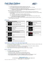
If no faults exist, then the Cooling Status (PLC output Y0) will turn on and then there is a 1 minute initial fluid
circulation delay which provides time for mixing of the fluids throughout the system.
(3)
Then the control starts monitoring the temperature every few seconds.
(4)
The program operates to maintain temperature between the Upper Deviation 1 (UD1) and the Lower Deviation 2
(LD2). Variations will occur depending on cooling operations and the heat load on the system.
-
When the Process Value (PV) temperature is at or above the UD1 value, then the Cooling Operation starts:
(1)
The first compressor will start with the hot gas valve (if included) energized, along with the control signal which
permits use of liquid line solenoid valve or fan relay (if included). The first compressor to operate is based on total
run time.
(2)
During the initial start of the first compressor, the low pressure switch fault is bypassed for approximately 20
seconds. If a low pressure fault is not present following the initial bypass, then the system continues in Cooling
Cycle Mode.
(3)
Thirty seconds after the first compressor starts, the hot gas valve will de-energize, if included.
-
When the PV is over the Upper Deviation 2, then the program will determine if temperature is increasing or decreasing:
Содержание ACWC-180-EM-DR-LT-0-5
Страница 35: ...Notes...
Страница 36: ...MAINTENANCE RECORD DATE PROCEDURE PERFORMED...

