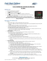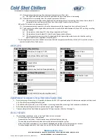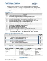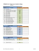
b.
The temperature controller parameters must
be setup for the lower leaving temperatures
that the system will generate.
c.
Also, some temperature thermostats may
need to be adjusted.
17.
PUMP (DEPENDING ON DESIGN)
a.
Systems with integral pump are typically
setup to provide recirculating fluid for the
chiller and some flow is routed for the process
system. Refer to the unit’s actual design for
details.
b.
A secondary pump may be used for process
specific applications, referred to as Process
Pump.
18.
TANK (DEPENDING ON DESIGN)
a.
Systems with integral tank will typically be
304 Stainless Steel with Open Top with
Shoebox Type Lid, Fluid Level Sight glass, Fill
Port, & Drain Plug.
19.
HEAT EXCHANGER (DEPENDING ON DESIGN)
a.
A heat exchanger is used to transfer heat
typically from the chiller fluid circuit to a
separate process fluid circuit.
20.
REMOTE OPERATION/STATUS PANEL (OPTION)
a.
Basic On/Off control switch with Cooling
Mode status and Fault indicator light.
21.
REMOTE OPERATION CONTROLS (OPTION)
a.
Various designs (contact Cold Shot Chillers for
options)
22.
SWITCHOVER SYSTEM (CHILLER BYPASS)
(
OPTIONS
)
a.
Manual City Switchover (MCSO) (Option)
a)
System valves which can be aligned to a
backup water supply system such as the
city water supply. Outlet fluid flow is
normally routed to the building’s drain
system. Valves are connected and must
be actuated simultaneously or in the
proper series to operate properly.
Converting back is normally performed in
the reverse order.
b.
Automatic City Switchover (See ACSO
literature)
a)
System has electrically operated valves
similar to MCSO, however it can be setup
to change automatically based on a
system safety situation.
23.
TANK LEVEL
(OPTIONS)
a.
Float Valve
a)
Located inside the tank, the float valve is
a mechanically float-actuated valve
supplied with a makeup water source of
fluid for the tank.
b)
The makeup water (such as city water
supply) is connected to the pipe
connection on the outside of the tank.
c)
Water pressure, typically, must be less
than 30psi.
d)
When the level falls below a certain level,
the valve will open and fill the tank.
When it reaches the top setting
adjustment, the valve closes.
e)
If the valve does not maintain level:
f)
Verify water pressure supply.
g)
Verify the float adjustment.
h)
Verify the mechanical linkages are free to
move.
i)
Verify there is no dirt or debris on the
valve seat.
b.
Tank Level Float Switch Solenoid Valve
a)
Tank Level Switches
b)
Float actuated switch(s) mounted in the
tank to monitor when tank is at different
levels depending on design such as:
a)
Safety – to stop the operation of
something such as the chiller or
pump.
b)
Notification – to provide a signal for
notification for manual refill or that
another action must be performed.
c)
Action – to provide signal for use
with other system uses such as
automatic fill systems.
c)
Low Tank Level- tank is at the low level
point that will/should begin filling the
tank. Above pump suction.
d)
High Tank Level- level in tank is at or near
top of tank and tank filling will/should
stop. Tank may overflow.
c.
Tank Level Float Controlled Solenoid Valve
a)
A solenoid valve is an electrically
operated valve to start and stop fluid flow
from an outside source of fluid such as
city water to refill tank, typically.
MNL_Standard-Basic_ACWC-24to240-E-(IN PROGRESS)_(0815).docx
- 12 -
Содержание ACWC-180-EM-DR-LT-0-5
Страница 35: ...Notes...
Страница 36: ...MAINTENANCE RECORD DATE PROCEDURE PERFORMED...


