Using Encoders with Line Scan Cameras
3
82
MVS-8600 Hardware Manual
Additionally, the interface offers the benefits of operating in differential signal mode (a
positive and negative signal pair) to increase noise immunity and the signal to noise ratio
(SNR), while reducing the effects of glitches and ground bounce in noisy electrical
environments. However, some differential encoders may not be directly connected to
the I/O without additional circuitry in order to meet the interface voltage and current
requirements.
Generally, most differential RS-422 compatible encoders will be compatible as long as
all the differential outputs are limited to the range 0 V to +5 V (absolute range referenced
to ground) which is often the case when using a +5 V power supply. It is also important
to note that the common mode voltage is the average of the voltage between the positive
and negative encoder signal pair. Unfortunately, most industrial environments have
limited DC power supply sources available, and often +12 V or +24 V is used for
encoders, resulting in a much higher voltage for the encoder signal outputs.
For encoders with signal outputs greater than +5 V (absolute reference to ground), the
signal needs to be made compliant with the input voltage requirements and properly
conditioned, given the effect of the circuit’s over voltage clamp.
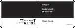
A simple solution is to utilize a series resistor in the path between each of the encoder
signal outputs. The resistor then functions as a voltage attenuation circuit. Its value is
determined through Ohm’s Law,
and depends on the
current loop through the 100 Ohm termination resistor. The wiring schematic is shown in
Figure 29 with the added series resistors labeled as R
1
and R
2
.
Figure 29. Schematic with series resistors
It is important to realize that the over voltage protection diode will clamp the input
voltage to a maximum of +5 V, and as such, there will be a maximum voltage drop
across R
1.
(When the polarity is switched, the clamp to ground is -0.3V for R
T
).
Additionally, in order to maintain balanced impedance for both the encoder positive
signal (V+) and encoder negative signal (V-), both R
1
and R
2
should be the same value.
In this case, the differential receiver circuit voltage input can be as low as +0.5 V (a ±
Voltage
Current Resis
ce
tan
=
Encoder
Output
Added Series
Resistors
8600 I/O
Te
rmi
na
to
r
100
Ω
R
1
R
2
R
T
V
V
Clamping Diodes
Содержание MVS-8000 Series
Страница 1: ...Cognex MVS 8000 Series MVS 8600 Hardware Manual September 2012...
Страница 6: ...Contents 6 MVS 8600 Hardware Manual...
Страница 10: ...Preface 10 MVS 8600 Hardware Manual NOTES...
Страница 42: ...MVS 8600 Installation 1 42 MVS 8600 Hardware Manual...
Страница 78: ...MVS 8600 Hardware 2 78 MVS 8600 Hardware Manual...