


128-6832
6 of 16
5
COMPLETING THE INSTALLATION
Adjusting the Shock Sensor
: Gently turn the adjustment knob counterclockwise to turn down the sensitivity
and turn clockwise to turn up sensitivity. Close the hood and trunk lids, and arm the alarm . Wait 6 seconds
for the accessories trigger zone to stabilize, then test the sensitivity adjust as needed
CAUTION: Never perform this test on the vehicle’s glass, as you may break the window.
WARNING !
Setting the sensitivity too high can cause false alarms due to noise vibrations from passing trucks
and heavy equipment. To decrease sensitivity, turn the adjustment screw counter clockwise.
Wire Dressing:
Always wrap the alarm wires in convoluted tubing, or with a spiral wrap of electrical tape.
Secure these looms along the routing using cable ties. This will ensure that the alarm wires are not
damaged by falling onto hot or sharp moving surfaces in the vehicle.
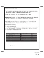
PROGRAMMABLE FEATURES
Changing Programmable Features:
This system has several programmable features that may need to be changed based on a specific vehicle or
a customer's preference. Programmable features can be changed using a bank of 7 dip switches located on the
side of the control module. To change a setting carefully flip the dip switch to the OFF position using a small
screwdriver or pick. Use the chart below as reference.
Dip Switch/Feature
ON
OFF
1) Passive Lock/30" Output when Armed
30 Sec Armed Output
Pass D/L
2) ARM/DISARM Input Polairty
POS
NEG
3) UNLOCK SENSE Input Polarity
POS
NEG
4) 1 or 2 Stage Unlock
2 Stage
1 Stage
5) Passive Arming
Passive
Active
6) Entry Delay
15 Seconds Delay
Instant
7) Siren/Horn Output
Siren
Horn
8) Door Ajar Warning
Instant
30 Secs.
Defalut Settings are in
BOLD


