5
2. THIRTEEN PIN HARNESS, CONTINUED
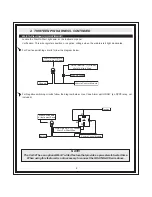
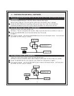
Parking Light Polarity (+/-) (WHITE/RED)
Parking Light Output (+/-) (WHITE)
Positive Switching Parking Lights:
Locate the parking light output wire at the vehicle’s light switch.
Verification: This wire registers positive voltage when the parking lights are turned on.
Connect the WHITE/RED wire to a 15 Amp max fused battery source.
Connect the WHITE wire to the parking light output wire at the vehicle’s light switch.
Negative Switching Parking Lights:
Locate the parking light output wire at the vehicle’s light switch.
Verification: This wire registers ground when the parking lights are turned on.
Connect the WHITE/RED wire to a good chassis ground.
Connect the WHITE wire to the parking light output wire at the vehicle’s light switch.
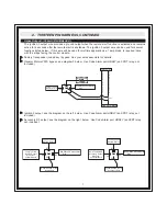
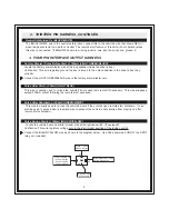
Ground When Armed Output (-) 300mA (ORANGE)
This wire will show Ground when the system is Armed. This wire is used for controlling window modules or
additional sensors.
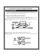
Tach Signal Input (PURPLE/WHITE)
Locate the vehicle’s ignition coil or fuel injector in the engine compartment.
Verification: Refer to Vehicle Wire Color and Location Chart for the wire color and location, or test using
the following procedure:
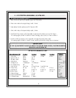
1. Set voltmeter to AC VOLTS.
2. Attach positive lead of the volt meter to a constant 12-volt source.
3. Attach negative lead of the volt meter to the wire being tested.
4. Start the engine.
5. Have someone press on the gas pedal slightly as you monitor the meter. If connected to the correct
wire, the voltage reading will increase as the engine’s RPM increases.
Connect the PURPLE/WHITE wire to the negative side of the vehicle ignition coil or fuel injector.
Содержание CA 521
Страница 16: ...16 ...


