


10
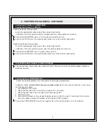
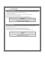
4. TWO PIN DOOR LOCK/UNLOCK HARNESS
Negative Lock Output (GREEN)
Negative Unlock Output (BLUE)
The door lock / unlock outputs are designed to control several different types of systems which may require
additional parts. Please review the wire and location chart to see which type of door lock system is in the
vehicle. The most common types are shown in the diagrams below.
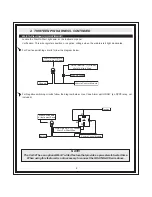
Negative Switching:
Locate the lock / unlock wires at the vehicle’s lock / unlock switch.
Verification: These wires will register ground when the lock/unlock switches are activated.
Connect the GREEN and BLUE wires shown in the diagram below.
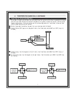
Positive Switching:
Locate the lock / unlock wires at the vehicle’s lock / unlock switch.
Verification: These wires will register positive voltage when the lock/unlock switches are activated
Connect the GREEN and BLUE wires shown in the diagram below.
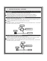
Reverse Polarity (5-Wire Door Locks)
Locate the lock / unlock wires at the vehicle’s lock / unlock switch.
Verification: These wires will rest at ground and register positive voltage when the lock/unlock switches are
activated.
Connect the GREEN and BLUE wires shown in the diagram below. Use Code Alarm part HDRLY (an SPDT
relay, not included).
30
87
87a
86
85
Cut
Fused +12 Volt
Battery Source
Lock
Unlock
Master Door
Lock Switch
X
30
87
87a
86
85
X
To Door Lock
Actuators
To Door Lock
Actuators
GREEN (-) Lock Output
BLUE (-) Unlock Output
Fused +12 Volt
Battery Source
Cut
Lock
Unlock
87
87a
86
85
30
87
87a
86
85
30
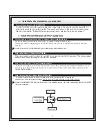
Vehicle Door Lock
Control Relays
Fused +12 Volt
Battery Souce
Fused +12 Volt
Battery Souce
GREEN (-) Lock Output
BLUE (-) Unlock Output
Positive Switching
Lock
Unlock
Vehicle Door Lock
Control Relays
GREEN (-) Lock Output
BLUE (-) Unlock Output
Negative Switching
Содержание CA 521
Страница 16: ...16 ...


