background image

Chapter 5:  Installation check and test

Test the system with SAILOR 6018

79

5555

Install

ation che

ck

 and 

5.4 Test the system with SAILOR 6018

5.4.1 Basic system verification

After powering the system, check 
that the upper right corner of the 
SAILOR 6018 display shows that the 
system is logged in and ready for use.

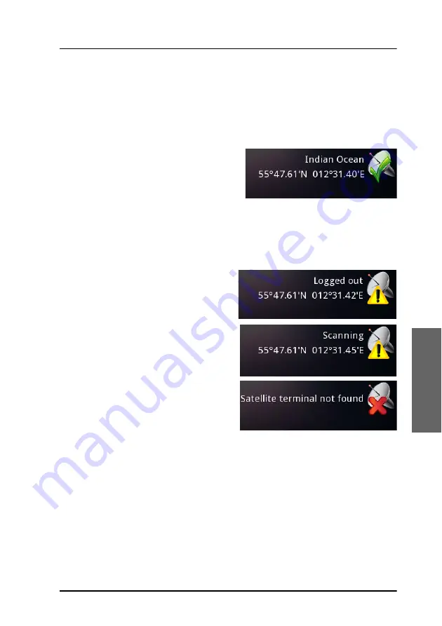
The system is logged in and ready when there is a green check mark at the 
satellite icon and the display shows the current position and the Ocean 
Region to which the system is logged on. 

If the system is not ready, the status field may show one of the following:

The SAILOR 3027 is logged out of 
the Inmarsat C network, but is 
synchronized with the satellite.

The SAILOR 3027 is not 
synchronized with a satellite, but is 
scanning for the best signal.

There is no connection between 
the SAILOR 3027 and the SAILOR 
6018.

Содержание SAILOR 6120

Страница 1: ...SAILOR 6120 30 40 50 Installation manual...

Страница 2: ......

Страница 3: ...i SAILOR 6120 30 40 50 Installation manual Document number 98 154541 A Release date November 15 2017...

Страница 4: ...ntent or accuracy of any translations or reproductions in whole or in part of this manual from any other source In the event of any discrepancies the English version shall be the governing text Thrane...

Страница 5: ...lose to the antenna When the system is powered make sure that nobody gets closer than the recommended minimum safety distance of 0 3 m 1 ft Dangers de rayonnements micro ondes Lors de transmissions l...

Страница 6: ...talling or servicing the system must be properly trained and authorized by Cobham SATCOM It is important that you observe all safety requirements listed in the beginning of this manual and install the...

Страница 7: ...em and shows wiring pin out and cable requirements Configuration describes the tools available and explains the initial configuration of the system Installation check and test contains a check list fo...

Страница 8: ...OR product covering installation commissioning and repair For details on available training classes please consult the Training Academy If the above link does not work go to cobham com satcom Select C...

Страница 9: ...27 14 Chapter 3 Connect the system 3 1 Connect the units 21 3 2 Ground the units 29 3 3 The CAN backbone 32 3 4 Connect power 33 3 5 Connectors and pinout 40 Chapter 4 Configuration 4 1 Register your...

Страница 10: ...t the system with easyMail 76 5 4 Test the system with SAILOR 6018 79 Chapter 6 Service and maintenance 6 1 Update the software 86 6 2 Maintenance guidelines 89 6 3 Service and repair 90 6 4 Available...

Страница 11: ...Table 8 SAILOR 6018 Ethernet connector pinout 43 Table 9 SAILOR 6018 CAN connector pinout 44 Table 10 SAILOR 6018 Power connector pinout 44 Chapter 4 Configuration Table 11 Supported LESes 70 Chapter...

Страница 12: ...List of tables x...

Страница 13: ...tions SAILOR 6120 30 40 50 system overview Units in the system 1 1 SAILOR 6120 30 40 50 system overview This manual describes four different systems SAILOR 6120 SSA System SAILOR 6130 LRIT System SAIL...

Страница 14: ...A buttons two alarm buttons and one test button which connect to the SAILOR 3027 SSA Terminal through the SAILOR 6194 Terminal Control Unit The CAN interface which connects the SAILOR 3027 SSA Termina...

Страница 15: ...n at least 4 times a day In addition to the basic Mini C functions listed in the next section the SAILOR 6130 LRIT System complies with the LRIT regulation and automatically reports the position of th...

Страница 16: ...acking and polling messaging logging and EGC Enhanced Group Call When used with a SAILOR 6194 Terminal Control Unit the SAILOR 6140 can be connected to a computer using either the LAN interface or the...

Страница 17: ...tems to send Distress alerts using the SAILOR 3042E In non SOLAS Distress systems a user interface is mandatory You can use the easyMail application installed on a computer or you can use a SAILOR 601...

Страница 18: ...C terminal The SAILOR 3027 comes in different variants for different systems The functions are different for each variant but the description below applies to all off these four variants SAILOR 3027 S...

Страница 19: ...power as well as bi directional communication For information on how to install the SAILOR 3027 see Install the SAILOR 3027 on page 14 1 2 2 SAILOR 6194 Terminal Control Unit The SAILOR 6194 is used f...

Страница 20: ...ion and test the system The SAILOR 6018 has a Distress button for sending Distress alerts and buttons for Mute Dim and Power The SAILOR 6018 has a touch screen interface and can be operated without a...

Страница 21: ...ial configuration on page 53 and SAILOR 6120 30 40 50 User manual 1 The following sections describe Unpack General installation requirements Install the SAILOR 3027 Mechanical installation of other un...

Страница 22: ...king material for future use After unpacking the system inspect it thoroughly for hidden damage and loose components or fittings If the contents are incomplete if there is mechanical damage or defect...

Страница 23: ...LOR 3027 Non SOLAS Terminal Pole mount kit for SAILOR 3027 Accessories kit including cables and connectors For details see Cables and connectors on page 28 Not included with SAILOR 6140 For SAILOR 612...

Страница 24: ...any power supply or battery that meets the power requirements listed in this section and in Appendix A Technical specifications Important Only the SAILOR 3027 mini C terminal must be placed outdoors P...

Страница 25: ...ties If you are using a battery make sure it is capable of providing the required power As a guideline note the power consumption of the following equipment Unit Idle power Max power SAILOR 3027 mini...

Страница 26: ...ty distance 1 ft 0 3 m Distance to exhaust fumes Do not place the terminal close to the funnel directly exposed to exhaust fumes Distance to heat Do not place the terminal close to any heat source Dis...

Страница 27: ...ion and the terminal must be minimum 29 x diameter of the obstruction Example The obstruction is a pole of 0 1 m diameter This means the terminal must be placed 29 x 0 1 m 2 9 m from the obstruction P...

Страница 28: ...cture hull This is very important in order to protect persons and equipment from lightning and safely bypass interference from Radar VHF MF HF radio equipment and other environmental sources of interf...

Страница 29: ...e mount kit 1 Lead the cable through the pole and pole mount adapter 2 Connect the CAN cable to the terminal 3 Mount cable relief for the CAN cable 4 Mount the adapter on the terminal using screws 5 T...

Страница 30: ...Do as follows 1 Attach the pole railing mount to the pole using the included nuts and spacers The drawings on the next page show the vertical and the horizontal assembly 2 Tighten the nuts 3 Place th...

Страница 31: ...Chapter 2 Install the system Install the SAILOR 3027 19 2222 Install the system Vertical pole Horizontal pole...

Страница 32: ...Chapter 2 Install the system 20 Install the SAILOR 3027 2 3 2 3 Mechanical outline drawing SAILOR 3027 170 5 164 6 M4 x 3 Length of thread 6 mm 120 157 145 Connector housing Conec 64...

Страница 33: ...e units The CAN backbone Connect power Connectors and pinout 3 1 Connect the units Before connecting the units read all sections in this chapter Connect the units according to the Wiring overview on t...

Страница 34: ...wiring of SSA buttons see SAILOR 6194 Terminal Control Unit Installation and user manual 3 Note In all the mini C systems you can also connect a computer For details see SAILOR 6120 30 40 50 with a co...

Страница 35: ...tem 3 1 1 2 SAILOR 6130 LRIT System and SAILOR 6140 Maritime system The drawing below shows the wiring of a basic SAILOR 6130 LRIT System or SAILOR 6140 Maritime System SAILOR 3027 LRIT Terminal CAN C...

Страница 36: ...below shows the wiring of a basic SAILOR 6150 Non SOLAS System with a computer You can connect two SAILOR 3042E Non SOLAS Alarm Panels to the system The second SAILOR 3042E must be connected to X12 w...

Страница 37: ...OR 6194 Terminal Control Unit Installation and user manual 3 Note The two alarm panels must share pin 1 in X10 6 25 7HUPLQDO RQWURO 8QLW 6 25 1RQ 62 6 7HUPLQDO 1 1 EXV LQFOXGLQJ SRZHU 1 6KLS JURXQG KX...

Страница 38: ...nel to the LAN interface on the SAILOR 6018 Note If you are using the SAILOR 6018 you will normally not need a SAILOR 6194 The SAILOR 6018 itself works as an alarm panel and you can connect additional...

Страница 39: ...through the CAN interface If the system is a SAILOIR 6120 SSA System or a SAILOR 6150 Non SOLAS System the SAILOR 6194 is delivered with your system The below drawing shows the wiring Instead of the c...

Страница 40: ...194 W3 NMEA 2000 Mini Device Cable Included 6 m with all systems except SAILOR 6140 W4 NMEA 2000 Micro Device Cable Included 6 m with SAILOR 6150 only W5 Straight through RS 232 serial cable with 9 pi...

Страница 41: ...power supply See page 16 in the section Location of the SAILOR 3027 mini C terminal 3 2 1 SAILOR 3027 mini C terminal You may use a special CAN cable containing only the power wires and shield to con...

Страница 42: ...on how to install the power supply see the documentation included with the power supply Ground plane connected to ship hull Ground stud Important When installing the power supply make sure you connec...

Страница 43: ...late of the SAILOR 6194 forms a ground plane for the electronic circuit This ground plane must be connected to ship ground in one of two ways Mount the SAILOR 6194 on a conducting surface connected to...

Страница 44: ...a separate termination resistance or inside the last device on the CAN backbone The SAILOR 6194 has a built in termination resistance The cable length from each device to the CAN T connector must be m...

Страница 45: ...12 3 4 2 Connect the power cables 3 4 2 1 SAILOR 3027 The SAILOR 3027 has one CAN connector which is also used for power input 1 Connect the red wire to DC and the black wire to DC in the power suppl...

Страница 46: ...to the correct under voltage protection Configure the under voltage protection as follows 1 Connect a computer to the SAILOR 6194 and start a terminal program as described in Configuration using comma...

Страница 47: ...ely together side by side to keep cable inductance low Ensure that cable inductance for the selected cable at the desired length is below the 50 uH requirement Refer to the data sheet for the cable yo...

Страница 48: ...n in Measure the ship source impedance on page 38 2 Find the resistance per m for the cable type you are going to use Table 5 shows typical cable resistance note that your cable type may differ from t...

Страница 49: ...0a 200a AWG 12 5 21 200a 200a 200a 200a AWG 13 6 57 200a a This is not the calculated length but the max CAN cable length from the mini C to the last unit on the CAN bus You must take into considerati...

Страница 50: ...follows 1 Measure the voltage without load R var disconnected 2 Set the current to e g 1 A by adjusting R var 3 Measure the corresponding voltage change 4 Calculate the source impedance from the volta...

Страница 51: ...r but do not connect the other end to the terminal 4 At the unconnected end of the CAN cable measure the source impedance as described in the next steps 5 Measure the voltage without load R var discon...

Страница 52: ...alone systems e g LRIT where you do not use the communication interface you only need to connect pin 2 and 3 to the power supply and the shield of the cable to ship ground at the power supply Importan...

Страница 53: ...ter and a keyboard You may also connect a USB memory stick LAN Ethernet interface Connects to the SAILOR 6194 Terminal Control Unit or an Ethernet switch in a local network ground stud Connects to shi...

Страница 54: ...a complete description and pin out for all connectors see SAILOR 6018 Message Terminal Installation manual 2 3 5 2 2 USB interface The USB connectors are USB Type A The figure and table below show the...

Страница 55: ...and table below show the connector outline and pin assignments Pin Pin function Wire color 1 Tx white orange 2 Tx orange 3 Rx white green 4 Not connected blue 5 Not connected white blue 6 Rx green 7 N...

Страница 56: ...2 5 Power input The figure and table below show the connector outline and pin assignments Pin Pin function Wire color 1 Not connected None 2 CAN_S Red 3 CAN_C Black 4 CAN_H White 5 CAN_L Blue Table 9...

Страница 57: ...onnecting additional equipment X5 and X6 are standard connectors for RS 232 9 pin D sub and Ethernet RJ 45 all other connectors are spring loaded terminals In the SAILOR 6120 SSA System the following...

Страница 58: ...monitoring equipment X3 and X13 are for future use X1 Power control is disabled by default but may be configured using a command For further information see SAILOR 6194 Terminal Control Unit Installa...

Страница 59: ...ni C system This chapter has the following sections Register your SAILOR 3027 Configuration tools Configuration using easyMail Configuration using SAILOR 6018 only for SAILOR 6150 Configuration using...

Страница 60: ...t are explained here The SAILOR 3027 must be registered at either a PSA company or directly to the ISP A PSA is a company handling the activation of Inmarsat mobiles and is short for Point of Service...

Страница 61: ...ment of calls for this MES through tick one a Accounting Authority AA b Inmarsat Service Provider ISP Enter ISP or AA Code If the Code is unknown enter the name of the ISP or AA NOTE If the terminal i...

Страница 62: ...nect your computer to the system The easyMail application is delivered on CD with the SAILOR 6194 Settings not available directly in the user interface can be accessed through the Terminal mode where...

Страница 63: ...cluded with the SAILOR 6194 into the CD drive of the computer The setup program should start up automatically If not run the file setup exe from the CD drive 2 Click Install easyMail and go through th...

Страница 64: ...SAILOR 6194 Terminal Control Unit TCU from the drop down list PC IP address Shows the IP address of your PC 4 Click OK easyMail now tries to establish a connection to the SAILOR 6194 and thereby the...

Страница 65: ...115200 4 Click OK easyMail now tries to establish a connection to the SAILOR 6194 and thereby the SAILOR 3027 When the RS 232 connection is established the PC connection bar at the top of the easyMail...

Страница 66: ...s you are now logged on 5 Select Setup Default ISP 6 Choose your Inmarsat Service Provider from the list 7 Select Setup Default LES 8 Choose the Land Earth Stations of your Inmarsat Service Provider f...

Страница 67: ...g the SAILOR 6018 is powered you can access the system settings from the SAILOR 6018 Settings not available in the graphical user interface can be accessed with the Mini C terminal mode in the SAILOR...

Страница 68: ...6018 The SAILOR 6018 can run Radiotelex or Inmarsat C 1 The SAILOR 6018 starts up on the Select application page 2 Select Inmarsat C and tap Store When you have selected and stored the Inmarsat C app...

Страница 69: ...To enter the mobile number in the SAILOR 3027 do as follows 1 In the SAILOR 6018 display select Network Settings Network ID 2 Enter the mobile number from your ISP and select OK The mobile number is...

Страница 70: ...at the bottom of the page The Power page shows details of both power supply and backup battery 3 Select Settings Important The default battery settings are suitable for most installations Do not chan...

Страница 71: ...the capacity of the battery larger battery higher charge current It must be high enough to charge the battery from empty to required capacity in 10 hours COMSAR Circ 32 6 Change the limits for alarms...

Страница 72: ...o set up use of Cyrillic characters 4 4 3 1 To enable Cyrillic characters 1 Select System from the main page 2 Select Settings from the bottom of the page 3 Select Regional settings 4 Select Cyrillic...

Страница 73: ...can do this either when you start a new message Message New message from the message editor Options New message from the message editor under the encoding format in the top right corner as shown below...

Страница 74: ...al mode A computer with easyMail in Terminal mode A computer with terminal program or telnet The next sections describe the different methods for entering commands 4 5 1 SAILOR 6018 in Mini C terminal...

Страница 75: ...exit and return to easyMail 4 5 3 Computer with terminal program telnet To enter commands using a computer you can use the serial RS 232 interface or the LAN interface 4 5 3 1 Using serial RS 232 port...

Страница 76: ...nect a computer to the LAN port of the SAILOR 6194 Terminal Control Unit which must be connected to your mini C system Refer to the SAILOR 6194 Terminal Control Unit Installation and user manual 3 for...

Страница 77: ...he SAILOR 3027 must be configured with the recipient s of the Ship Security Alert The recipients must be selected according to the Flag Administration under which the vessel is sailing The recipients...

Страница 78: ...Syntax for SSA recipient command Syntax se am entry type address param entry 0 5 type 0 Telex 1 Fax add t30 at the end see example for fax below 6 SMS add the LES use code at the end see example for...

Страница 79: ...8888 enter the following command line se am 0 1 4539558888 t30 entry 0 for the first entry type 1 for fax address 4539558888 fax number param t30 fax numbers must always have this parameter at the end...

Страница 80: ...with the email address xxx cobham com enter the following command line se am 0 254 xxx cobham com entry 0 for the first entry type 254 for email address xxx cobham com email address 4 6 1 6 Multiple a...

Страница 81: ...is to inform the recipient that a SSAS configuration change has been made 0 Do not send configuration change message 1 Send a configuration change message to the address configured for this entry Exa...

Страница 82: ...Note that the list is dynamic so it may not be completely up to date Service Provider LES no AOR W LES no AOR E LES no POR LES no IOR CTTC China 211 311 KDDI SatMail C Japan 003 103 203 303 Morsviazs...

Страница 83: ...To configure the SSA button type to standard operational mode enter cfg c 0 4 6 3 To change the SSA message repeat rate The repeat rate is the time between two SSA messages until the alert is cancell...

Страница 84: ...cation To define whether or not you have to push the test button on board to access the configuration use the following command se ab 0 you can change settings without pushing the test button on board...

Страница 85: ...shows how to make an initial test of the system This chapter has the following sections Installation check list Test the SAILOR 6130 LRIT System Test the system with easyMail Note The SAILOR 6120 30...

Страница 86: ...Away from exhaust fumes Minimum safety distance to people Minimum distance to other equipment Are all cables connected correctly Power cables Wiring overview on page 22 and Connect power on page 33 C...

Страница 87: ...SAILOR 3027 LRIT Terminal The LESO returns the result of the test which is either that the mobile passed or failed the test A written result may look like this Any further requirements for testing are...

Страница 88: ...ase the PC has not established a connection to the SAILOR 3027 nor the SAILOR 6194 if present If you are using RS 232 the reason may be that the COM port in the PC is already open by another applicati...

Страница 89: ...1 In the easyMail application click Distress Distress Test Mode A popup shows that the system is in Distress test mode 2 Press and hold the alert button on the SAILOR 3042E for at least 5 seconds Dur...

Страница 90: ...for performing the Link test This can take a short while 3 When the Linktest window appears click Execute to start the test A popup informs you that the test has started When the test has ended anothe...

Страница 91: ...The system is logged in and ready when there is a green check mark at the satellite icon and the display shows the current position and the Ocean Region to which the system is logged on If the system...

Страница 92: ...Terminal has a test function that allows test of the Inmarsat C Distress Buttons Distress LEDs and wiring To test the Inmarsat C Distress buttons in the system do as follows 1 In the SAILOR 6018 disp...

Страница 93: ...llowing window appears As long as the Test in progress window is showing you can use Distress buttons connected to the system under test without sending a real Distress Alert Important Before pushing...

Страница 94: ...to send a real Distress alert click Cancel in the Test in progress window Note Before pushing any Distress buttons check the units as follows If an alarm panel is connected to the SAILOR 6018 On the a...

Страница 95: ...ink test using the SAILOR 6018 do as follows 1 In the SAILOR 6018 display select Network 2 Select Status 3 Select Link test The Link test window shows the result of the latest link test if any 4 Selec...

Страница 96: ...Chapter 5 Installation check and test 84 Test the system with SAILOR 6018...

Страница 97: ...and maintenance 6 This chapter describes how to maintain and handle the units in the system and how to update software This chapter has the following sections Update the software Maintenance guidelin...

Страница 98: ...e g the SAILOR 3027 SAILOR 6101 03 and SAILOR 6194 use the TMA ThraneLINK Management Application For information on how to install the TMA see the next sections 6 1 1 2 The ThraneLINK Management Appl...

Страница 99: ...cate the ThraneLINK Management Application software package and download it to your PC 5 Extract the files from the zip file 6 Click setup exe to start the installation wizard On Windows Vista 7 8 10...

Страница 100: ...3 Insert a USB memory stick with the new software version placed in the root into a USB connector in the PC 1 The TMA automatically discovers the new software version s and a software update icon flas...

Страница 101: ...erminal must be replaced by qualified personnel 6 2 1 Precautions for handling the SAILOR 3027 Do not expose the joints of the SAILOR 3027 mini C terminal or the connector to high pressure water jets...

Страница 102: ...or sending the product for repair Your dealer installer or Cobham SATCOM partner will also take care of any warranty issue 6 3 1 Repack for shipment Should you need to send the product for repair plea...

Страница 103: ...ine Micro termination Connector 406100 933 Male Mini NMEA 2000 Field Connector 406100 934 Male Micro NMEA 2000 Field Connector 406100 940 6 m NMEA 2000 Micro Device Cable 406100 941 20 m NMEA 2000 Mic...

Страница 104: ...ount kit 6 4 3 Plate washer for SAILOR 3027 Part number Item 403027 103 Adjustable pole railing mount kit for SAILOR 3027 Table 14 Adjustable pole railing mount kit part number Part number Item 403027...

Страница 105: ...units in the SAILOR 6120 30 40 50 refer to the installation manuals for the individual units A 1 SAILOR 6120 30 40 50 specifications For further information on compliance and certificates refer to the...

Страница 106: ...degrees elevation Datum format WGS84 Inmarsat Protocol services Message transmission and reception with IA 5 ITA 2 and binary transfer to from Telex PSTN telephone modems and fax modems EGC message re...

Страница 107: ...0 5 32 VDC 15 VDC nominal Max power 30 W Max continuous current 2 8 A Max peak current 4 A startup Standby power Rx mode 2 W Sleep Mode power 10 mW Compass safe distance 5 m Weight 1 10 kg without pol...

Страница 108: ...hour 87 mph Wind Wind speed up to 200 km hour 124 mph Vibrations operational Random 5 20 Hz 0 005 g2 Hz 20 150 Hz 3dB oct 0 5g RMS Vibrations survival Random 5 20 Hz 0 05 g2 Hz 20 150 Hz 3 dB oct 1 7...

Страница 109: ...ork Identifier An address code to an electronic mailbox at the Land Earth Station E EGC Enhanced Group Call A type of broadcast data for ships EIRP Effective Isotropically Radiated Power The amount of...

Страница 110: ...rminal manufacturer to each newly manufactured terminal for Inmarsat s satellite networks ISP Inmarsat Service Provider The company providing the Inmarsat services L LAN Local Area Network A computer...

Страница 111: ...sonars anemometer wind speed and direction gyrocompass autopilot GPS receivers and many other types of instruments It has been defined by and is controlled by the U S based National Marine Electronic...

Страница 112: ...of transmitting a security alert to the shore not to other vessel to indicate to a competent authority that the security of the ship is under threat or has been compromised T TMA ThraneLINK Management...

Страница 113: ...A buttons 65 tools for 50 with commands 62 with easyMail 51 connectors Message Terminal 41 SAILOR 3027 40 SAILOR 6018 41 SAILOR 6194 45 Cyrillic characters keyboard 61 set up in Message Terminal 60 D...

Страница 114: ...max lengths 36 power consumption 13 power limits configuring 58 power requirements 12 R registration 48 repacking for shipment 90 returning units 90 RS 232 communication with easyMail 52 S safety dist...

Страница 115: ...3 Index T ThraneLINK Management Application 86 TMA 86 installing 87 tools for configuration 50 typography used in this manual vi U under voltage protection 34 user interface 50 W warranty 90 wiring of...

Страница 116: ...98 154541 A www cobham com satcom...

Отзывы: