MODEL CMA-180UC SERVICE & PARTS MANUAL Rev. 1.18B
Page
9
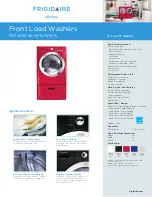
Figure 2.2.4
Note:
In Figure 2.2.4 the machine’s wire harness was left out of the back of the
power block to more clearly show the dispenser wires.
2. Remove the plug from the mixing chamber located by the vacuum breaker on the
back of machine; and install the rinse injection fitting (supplied with your
dispenser). See Figure 2.2.4.
Figure 2.2.4.
3. A 7/8" detergent injection hole is provided in the back of the wash tank. Remove
the S.S. plug and install the detergent fitting (supplied with your dispenser).
4. The final step of installing the CMA supplied Detergent and Rinse Dispenser is
programming it to your specific application. The reference manual supplied with
the dispenser shows you how to program it.
Keep in mind while reading the reference manual that the CMA-180UC
operates in “probe-less” mode. (This mode is selected by setting a value of
“2” in screen 21).
Screen 22 must be set to “1” (Door).
Multi-conductor cable
Black (Main Power)
Note:
Machine Neutral
(White wires)
Detergent Signal wires
(Red terminals)
Rinse Signal wires
(Blue terminals)
Gray/Violet
(Main Power Neutral)
(Same terminal as rinse neutral)
Brown (LIVE) wire
Содержание CMA-180UC
Страница 13: ...MODEL CMA 180UC SERVICE PARTS MANUAL Rev 1 18B Page 11 2 2 6 Water Tempering Kit ...
Страница 16: ...Operation MODEL CMA 180UC SERVICE PARTS MANUAL Rev 1 18B Page 14 3 3 Operating and Cleaning Instructions ...
Страница 17: ...Operation MODEL CMA 180UC SERVICE PARTS MANUAL Rev 1 18B Page 15 3 4 Preventive Maintenance Chart ...
Страница 40: ...Parts Manual MODEL CMA 180UC SERVICE PARTS MANUAL Rev 1 18B Page 38 5 Electrical Diagram ...
Страница 41: ...Parts Manual MODEL CMA 180UC SERVICE PARTS MANUAL Rev 1 18B Page 39 ...