MODEL CMA-180UC SERVICE & PARTS MANUAL Rev. 1.18B
Page
3
1.2.
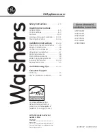
CMA-180UC Operational Cycle
The CMA-180UC Operational Cycle has a total cycle time of 2 minutes (120 seconds). The
Timing Diagram and the steps listed below detail the individual functions that are executed
during each Operational Cycle.
Seconds:
0
10
20
30
40
50
60
70
80
90
100
110
120
1.
With the machine powered up toggling the START switch begins a cycle.
a)
Toggling the START switch energizes both the Cam Timer motor and the Instant Start
Relay. The Instant Start Relay latches ON the power to the Cam Timer motor so that
the START switch can be released a moment after it has been toggled without the Cam
Timer motor losing power.
b)
After about 1.5 seconds the Cam Timer’s first cam—the Cam Timer Motor Cam—
latches ON the power to the Cam Timer motor and drops out the Instant Start Relay.
The Cam Timer motor continues to run for a total of 2 minutes, at which time it
switches OFF—resetting the Cam Timer—and waits for the next START command.
2.
The Cam Timer’s third cam controls the Wash Pump. The Wash Pump comes ON about 3
seconds into the Operational Cycle and continues to run for 94 seconds. This 94-second
period is the Wash Cycle.
3.
At the same time that the Wash Pump comes ON the Cam Timer’s fourth cam powers ON
the Optional Drain Pump—if one is present—and keeps it running for about 7 seconds
before powering OFF. This cam turns ON again midway through the Rinse Cycle and
stays ON for 10 seconds, turning OFF 2 seconds after the Rinse Cycle has completed.
4.
About 3 seconds after the Wash Cycle has completed the Cam Timer’s second cam, which
controls the Rinse Cycle, turns ON—energizing the Water Solenoid—and stays ON for 16
seconds. This 16-second period is the Rinse Cycle.
Instant
Start Relay
Cam Timer
Motor Cam
Rinse Cycle
Cam
Wash Cycle
Cam
Optional Drain
Pump Cam
Safe-T-
Temp Cam
Содержание CMA-180UC
Страница 13: ...MODEL CMA 180UC SERVICE PARTS MANUAL Rev 1 18B Page 11 2 2 6 Water Tempering Kit ...
Страница 16: ...Operation MODEL CMA 180UC SERVICE PARTS MANUAL Rev 1 18B Page 14 3 3 Operating and Cleaning Instructions ...
Страница 17: ...Operation MODEL CMA 180UC SERVICE PARTS MANUAL Rev 1 18B Page 15 3 4 Preventive Maintenance Chart ...
Страница 40: ...Parts Manual MODEL CMA 180UC SERVICE PARTS MANUAL Rev 1 18B Page 38 5 Electrical Diagram ...
Страница 41: ...Parts Manual MODEL CMA 180UC SERVICE PARTS MANUAL Rev 1 18B Page 39 ...