6
Brake Cluster Removal and Installation
BRAKE SYSTEM
3.
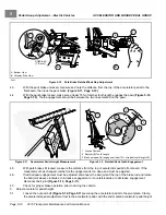
Test drive vehicle. Be sure the brakes function properly. When brake pedal is fully pressed under moderate
pressure, it should not go more than halfway to floor, and the vehicle should come to a smooth, straight stop. If
the brake pedal goes more than halfway to the floor, or if the vehicle swerves or fails to stop, check pedal group
adjustment, and readjust cable tension and brakes.
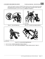
See Brake Cable Equalization on page 6-10. See Final
Brake Cluster Adjustment on page 6-11.
Brake adjustment must be maintained so the brake pedal cannot be
pressed to the floor under any circumstance.
BRAKE CLUSTER REMOVAL AND INSTALLATION
See General Warnings on page 1-2. See also Asbestos Dust Warning on page 6-1.
FRONT BRAKE CLUSTER REMOVAL
1.
Place chocks at rear wheels, loosen lug nuts on front wheels, and lift the front of the vehicle with a chain hoist or
floor jack. Place jack stands under the round tube crossmember of the frame to support vehicle.
2.
Release park brake.
3.
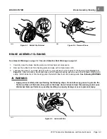
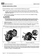
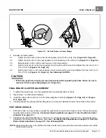
Loosen the equalizer retaining nuts (1 and 6) on the front equalizer rod (2) to slightly loosen the brake cable
.
4.
Remove the front wheels and then the brake drums.
5.
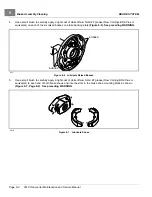
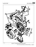
Remove bow-tie pin (17) and clevis pin (16) from brake cable
(Figure 6-21, Page 6-15) (Figure 6-20, Page 6-13)
.
6.
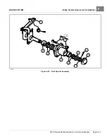
Remove dust cap (6) on hub and bearing assembly.
7.
Remove cotter pin (5) and hex nut (7) from spindle shaft
.
8.
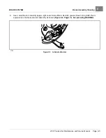
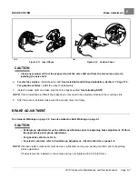
Remove hub and bearing assembly from spindle shaft. Remove four bolts (22), cone washers (21), lockwashers
(20), and hex nuts (19) that mount the brake cluster to the spindle
9.
Remove brake cluster assembly from spindle.
FRONT BRAKE CLUSTER INSTALLATION
1.
Install in reverse order of removal. Use bolts (22), cone washers (21), lock washers (20), and hex nuts (19) to
mount brake cluster
.
2.
Tighten bolts to 30 ft·lb (41 N·m). Adjust brakes as previously described in this section. Use new bow-tie pins
when reconnecting brake cables.
Page 6-12
2019 Transporter Maintenance and Service Manual
Содержание TransPorter 4
Страница 2: ......
Страница 18: ...Pagination Page 1 General Warnings SAFETY Page 1 6 2019 Transporter Maintenance and Service Manual ...
Страница 112: ...8 Tires WHEELS AND TIRES Figure 8 2 Inflate Tire Page 8 4 2019 Transporter Maintenance and Service Manual ...
Страница 271: ...ELECTRIC MAIN HARNESS Wiring Diagrams Electric Main Harness 18 ...
Страница 272: ... Page intentionally left blank ...
Страница 273: ...ELECTRIC INSTRUMENT PANEL HARNESS Wiring Diagrams Electric Instrument Panel Harness 18 ...
Страница 274: ... Page intentionally left blank ...
Страница 275: ...ELECTRIC ACCESSORIES HARNESS Wiring Diagrams Electric Accessories Harness 18 ...
Страница 276: ... Page intentionally left blank ...
Страница 282: ...NOTES ...
Страница 283: ...NOTES ...
Страница 284: ...NOTES ...
Страница 285: ......
Страница 286: ......

