ELECTRICAL SYSTEM TROUBLESHOOTING
Test Procedures
12
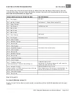
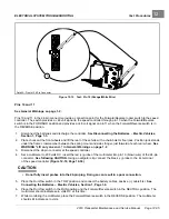
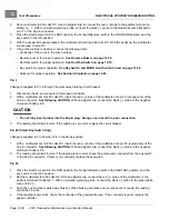
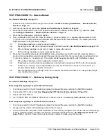
If the results of any of the referenced procedures are different from those described in the procedure, check the
continuity of the wires in the wire harness and test the connected components with the appropriate test procedures.
(See Index of Test Procedures on page 12-11).
_
SPEED CONTROLLER 24-PIN CONNECTOR WIRE
TEST PROCEDURE
Pin 1 – Tan (18-gauge)
KEY INPUT
Pin 2 – Light Blue (18-gauge)
Test Procedure 11 – Charger Interlock on page 12-23
Pin 3 – Orange (18-gauge)
Pin 4 – Gray (18-gauge)
Test Continuity of wire
Pin 5 – Open (no wire)
Pin 6 – Open (no wire)
Pin 7 – Open (no wire)
Pin 8 – Green (18-gauge)
FOOT INPUT
Pin 9 – Pink (18-gauge)
Test continuity of wire
Pin 10 – Brown (18-gauge)
Pin 11 – Red/Green (18-gauge)
Pin 12 – Open (no wire)
Pin 13 – White (18-gauge)
Pin 14 – Purple/White (18-gauge)
Pin 15 – Yellow (18-gauge)
Test continuity of each wire and perform
Pin 16 – Open (no wire)
Pin 17 – Blue/White (18-gauge)
Pin 18 – Open (no wire)
Pin 19 – Orange/White (18-gauge)
Pin 20 – Purple (18-gauge)
Pin 21 – White/Black (18-gauge)
Supplies approximately 13 volts to the Guardian/Visage unit.
CONNECTED CAR OUTPUT
Approximately 13 volts measured between pin 1 and B- terminal on
controller (Key switch either ON or OFF)
Pin 22 – Blue/Yellow (18-gauge)
Supplies a positive (+), controlled current source to power the charge
indicator light on the instrument panel.
CHARGE INDICATOR LIGHT OUTPUT
Start a charging session. After a few seconds, light should flash. Can
also be seen under LED Driver in the Monitor menu of the CDT.
Pin 23 – Green/White (18-gauge)
Pin 24 – Open (no wire)
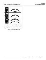
Pins 13, 14, and 15
See General Warnings on page 1-2.
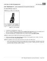
Pins 13, 14, and 15 in the 24-pin connector provide a connection point from the MCOR potentiometer to the speed
controller.
2019 Transporter Maintenance and Service Manual
Page 12-31
Содержание TransPorter 4
Страница 2: ......
Страница 18: ...Pagination Page 1 General Warnings SAFETY Page 1 6 2019 Transporter Maintenance and Service Manual ...
Страница 112: ...8 Tires WHEELS AND TIRES Figure 8 2 Inflate Tire Page 8 4 2019 Transporter Maintenance and Service Manual ...
Страница 271: ...ELECTRIC MAIN HARNESS Wiring Diagrams Electric Main Harness 18 ...
Страница 272: ... Page intentionally left blank ...
Страница 273: ...ELECTRIC INSTRUMENT PANEL HARNESS Wiring Diagrams Electric Instrument Panel Harness 18 ...
Страница 274: ... Page intentionally left blank ...
Страница 275: ...ELECTRIC ACCESSORIES HARNESS Wiring Diagrams Electric Accessories Harness 18 ...
Страница 276: ... Page intentionally left blank ...
Страница 282: ...NOTES ...
Страница 283: ...NOTES ...
Страница 284: ...NOTES ...
Страница 285: ......
Страница 286: ......

