CLIVET ELFOROOM 11 Скачать руководство пользователя страница 92


1.2  

GENERALITE  

Préliminaires 


Le lieu d'installation, les systèmes hydraulique, frigorifique et 
électrique, et les canalisations de l'air doivent être définies par 
le concepteur de l'installation en accord avec la législation 
locale en vigueur. 

L'unité doit être installée, testée et assistée par du personnel 
qualifié satisfaisant aux exigences de la loi. 

Désactiver immédiatement l’unité en cas de panne ou 
mauvais fonctionnement:  

• 

fait déchoir la garantie  

• 

peut compromettre la sécurité d'emploi de l'unité  

• 

peut augmenter les coûts et les délais de réparation. 

L’installation doit être effectuée en se conformant aux normes 
de sécurité locales.  
Le matériel d'emballage  constitue une source potentielle de 
danger. Il doit par conséquent être conservé hors de portée 
des enfants. 
Recycler et éliminer le matériel d’emballage conformément 
aux normes locales. 

Situations de risque 


L’unité est conçue et construite de manière à ne pas exposer 
la santé et la sécurité des personnes à des risques.  
Au moment de la conception n’est pas possible intervenir sur 
toutes les causes de risque.  
Lire la section "Risques  résiduels" qui indique les situations 
qui peuvent blesser des personnes ou endommager des 
choses.  
Installation, mise en marche, entretien et réparation exigent 
des connaissances spécifiques; s’ils sont performées par  
personnel inexpert peuvent blesser des personnes ou 
endommager des choses.  

Destination d'emploi 


L'unité est conçue uniquement pour le refroidissement/
chauffage d'eau ou d'eau glycolique à des fins de 
climatisation, en respectant les limites prévues sur la notice 
technique et le présent manuel. 

Le fabricant ne saurait être retenu responsable en cas de 
toute autre utilisation. 

Installation


Vérifier que les caractéristiques du réseau électrique sont 
conformes aux données figurant sur la plaquette de matricule 
de l'unité. 

Entretien


Prévoir des contrôles et des opérations périodiques de 
maintenance pour prévenir et limiter les coûts de réparation.  
Couper la tension électrique avant d'effectuer toute opération 

Modifications


Le fabricant décline toute responsabilité avec annulation de la 
garantie en cas de quelconque modification. 

Panne ou fonctionnement défectueux


Désactiver immédiatement l’unité en cas de panne ou 
mauvais fonctionnement. 
S'adresser à un centre d'assistance technique agréé. 
Demander l'utilisation de pièces de rechange originales. 

Formation utilisateur


L’installateur doit instruire l’utilisateur, en particulier sur   

• 

allumage/arrêt 

• 


modification du point de consigne 

• 


Jachère;


• 


entretien 

• 


qu'est-ce qu’on peut faire/pas faire en cas de panne 

Mise a jour des données 


Les améliorations continuelles apportées au produit peuvent 
entraîner des variations des données indiquées. 

Consulter le site web du constructeur pour obtenir les 
données mises à jour . 

Conserver avec le schéma électrique et les mettre à la 
disposition de l'opérateur . 

Transcrire les données d'identification de l'unité de manière à 
pouvoir les fournir au service après-vente en cas de demande 
d'assistance (voir le paragraphe “Identification de l'unité”).  

Prévoir un livret réservé à l'unité où reporter les interventions 
effectuées sur l'unité, ce qui permettra de mieux planifier les 
différentes interventions et de faciliter la recherche 
d'éventuelles anomalies.  
En cas de panne ou mauvais fonctionnement: 

• 

désactiver immédiatement l’unité  

• 

s'adresser à un centre d'assistance technique agréé . 

• 

Demander l'utilisation de pièces de rechange originales . 

Demander à l'installateur de bien vous informer sur: 

• 

allumage/arrêt  

• 

modification du point de consigne  

• 

jachère  

• 

entretien  

• 

qu'est-ce qu’on peut faire/pas faire en cas de panne . 

1.3 INDICATIONS POUR L'UTILISATEUR 


1 - GENERALITE


Ce manuel a été réalisé afin de permettre une installation, une 
mise au point et un entretien corrects de l'unité. 

Faire particulier attention à :  

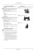
AVERTISSEMENTS pour identifier des opérations ou des 
informations particulièrement importantes  

INTERDICTIONS opérations interdites, susceptibles de 
compromettre le fonctionnement de l'unité ou de causer des 
dommages aux biens ou aux personnes.  

• 

Il est fondamental que les instructions qui suivent soient 
lues le plus attentivement possible 

• 

Suivre les indications pour ne pas causer la blessure des 
personnes ou l’endommagent des choses. Il faut lire les 
informations préliminaires avant d'effectuer toute 
opération. 

1.1  MANUEL


92

Содержание ELFOROOM 11

Страница 1: ... INSTALLAZIONE E MANUTENZIONE pagina 3 GB ISTALLATION AND MAINTENANCE MANUAL page 45 F MANUEL D INSTALLATION ET D ENTRETIEN page 89 E MANUAL DE INSTALACIÓN Y USO página 133 D ANLEITUNG ZUR INSTALLATION UND WARTUNG Saite 177 RU ИНСТРУКЦИЯ ПО УСТАНОВКЕ И ЭКСПЛУАТАЦИИ страница 221 ...

Страница 2: ...o dell azienda è quello di portare ai propri clienti sistemi evoluti che assicurino il comfort migliore riducano i consumi di energia i costi di installazione e di manutenzione per l intero ciclo di vita del sistema Con questo manuale desideriamo fornire informazioni che potranno essere utili in tutte le fasi dalla ricezione all installazione all utilizzo e fino allo smaltimento affinché un sistem...

Страница 3: ... 1 2 3 4 Generalità 4 Ricevimento 7 Posizionamento 8 Collegamenti idraulici 11 Collegamenti elettrici 16 Regolazione 23 Manutenzione 34 Dismissione 37 Informazioni tecniche 38 Rischi residui 42 5 6 7 8 9 10 3 ...

Страница 4: ... la responsabilità del costruttore Guasto o funzionamento difettoso Disattivare subito l unità in caso di guasto o malfunzionamento Rivolgersi ad un centro assistenza autorizzato dal costruttore Richiedere l utilizzo di ricambi originali Formazione utilizzatore L installatore deve istruire l utilizzatore in particolare su Accensione spegnimento Modifica setpoint Messa a riposo Manutenzione Cosa fa...

Страница 5: ...te di pericolo È vietato salire con i piedi sull apparecchio e o appoggiarvi qualsiasi tipo di oggetto L apparecchio può raggiungere temperature sui componenti esterni superiori ai 70 C PRESTARE MOLTA ATTENZIONE AL CONTATTO PERICOLO SCOTTATURE 1 4 REGOLE FONDAMENTALI DI SICUREZZA 1 5 IDENTIFICAZIONE DELLA MACCHINA Etichetta matricolare L etichetta matricolare è posizionata sull unità generalmente ...

Страница 6: ...lo con opzioni 3V010 HIDE2X Controllo ambiente semplificato E I 3V on off per installazione a muro disponibile solo con opzioni 3V010 HIDE3X Controllo ambiente plurifunzionale per installazione a muro disponibile solo con opzioni 3V010 HID T2X Controllo ambiente elettronico HID T2 esterno solo temperatura HID T3X Controllo ambiente elettronico HID T3 esterno temperatura e umidità HID TI2X Controll...

Страница 7: ...enzione a non danneggiare l unità Riciclare e smaltire il materiale di imballaggio secondo le norme locali 2 1 INFORMAZIONI PRELIMINARI 2 RICEVIMENTO Prima di accettare la consegna controllare Che l unità non abbia subito danni nel trasporto Che il materiale consegnato corrisponda a quanto indicato sul documento di trasporto confrontando i dati con l etichetta matricolare posizionata sull imballo ...

Страница 8: ...zi funzionali indicati in figura Evitare l installazione dell unità in prossimità di posizioni soggette all esposizione diretta dei raggi solari in prossimità di fonti di calore in ambienti umidi e zone con probabile contatto con l acqua in ambienti con vapori d olio in ambienti sottoposti ad alte frequenze Accertarsi che la parete su cui si intende installare l unità abbia una struttura e una por...

Страница 9: ... due viti posteriori Forare con una punta adeguata ed infilare i tasselli 2 per ogni staffa fig 3 1 rif A fissare le due staffe fig 3 1 rif B Non stringere eccessivamente le viti Infilare la macchina sulle due staffe mantenendola in posizione quindi fissare le due viti nei tasselli posteriori fig 3 1 rif C una per ogni lato Si raccomanda di conferire un adeguata inclinazione dell unità verso il tu...

Страница 10: ... Forare con una punta adeguata ed infilare i tasselli 2 per ogni staffa fig 3 3 rif A fissare le due staffe fig 3 3 rif B Non stringere eccessivamente le viti in modo da poter effettuare una regolazione delle staffe con una bolla di livello fig 3 4 Bloccare definitivamente le due staffe serrando completamente le quattro viti Verificarne la stabilità spostando manualmente le staffe verso destra e s...

Страница 11: ...re a 1 Nell installazione verticale il tubo di scarico si collega direttamente alla vaschetta di scarico posizionata in basso sulla spalla laterale sotto gli attacchi idraulici Nell installazione orizzontale il tubo di scarico viene allacciato a quello già presente sulla macchina Se possibile fare defluire il liquido di condensa direttamente in una grondaia o in uno scarico di acqua bianche In cas...

Страница 12: ...data e ritorno fino all imbocco della macchina in modo da impedire gocciolamenti di condensa all esterno della bacinella di raccolta stessa coibentare il tubo di scarico della condensa della bacinella per tutta la sua lunghezza 4 4 ROTAZIONE ATTACCHI Le operazioni descritte e le immagini relative si riferiscono ad una macchina con attacchi a sinistra su cui necessita la rota zione degli attacchi s...

Страница 13: ... dei collegamenti elettrici Sfilare i cablaggi all interno della macchina e reinfilarli dal lato opposto Utilizzare per la connessione del motore l apposito cablaggio per attacchi a destra disponibile come accessorio Invertire le posizioni di montaggio dello sportellino fig 4 6 rif A con il pannello di comando fig 4 6 rif C e rimontarli nelle rispettive posizioni Smontare la vaschetta di raccolta ...

Страница 14: ...condensa centrale fig 4 7 rif G portare la vaschetta in appoggio sul lato opposto in modo che dalla struttura fuoriesca il bocchettone di attacco per la prolunga rompigoccia indi bloccare la bacinella con la vite precedentemente smontata reinfilare la prolunga rompigoccia e sul lato opposto il tappo ruotare lo scambiatore portando gli attacchi sul lato opposto e reinfilarlo sulla macchina avvitare...

Страница 15: ...dell impianto manuali o automatici Iniziare il riempimento aprendo lentamente il rubinetto di carico acqua impianto Per i modelli installati in posizione verticale agire utilizzando un cacciavite sullo sfiato della batteria posto più in alto fig 4 9 rif A per gli apparecchi installati in posizione orizzontale agire sullo sfiato posizionato più in alto fig 4 9 rif B Quando comincia ad uscire acqua ...

Страница 16: ...nuale sono riferiti all unità standard accessori esclusi Fare quindi riferimento ai dati riportati in etichetta matricolare 5 2 DATI ELETTRICI 5 3 COLLEGAMENTI 1 Fare riferimento allo schema elettrico dell unità il numero di schema elettrico è indicato nell etichetta matricolare 2 Verificare che la rete abbia caratteristiche conformi ai dati riportati sulla targhetta matricolare 3 Prima di iniziar...

Страница 17: ... raffreddamento chiller contatto pulito max 1A SW2 ON OFF remoto H2 sonda temperatura acqua 4T riscaldamento 2T raffreddamento riscaldamento H4 sonda temperatura acqua 4T raffreddamento S1 microinterruttore sicurezza griglia Y1 Elettrovalvola acqua 4T riscaldamento 2T riscaldamento raffreddamento Y2 Elettrovalvola acqua 4T raffreddamento 4 tubi Y1 Y2 2 tubi Y1 17 ...

Страница 18: ...W2 ON OFF remoto H2 sonda temperatura acqua 4T riscaldamento 2T raffreddamento riscaldamento H4 sonda temperatura acqua 4T raffreddamento S1 microinterruttore sicurezza griglia off ventilazione spenta a setpoint soddisfatto Y1 Elettrovalvola acqua 4T riscaldamento 2T riscaldamento raffreddamento Y2 Elettrovalvola acqua 4T raffreddamento Opzione radianti vedere 5 6 TERMOSTATO HID Ti2 TERMOSTATO HID...

Страница 19: ...Bus RS485 2 ELFOControl Home 3 GAIA 4 ELFOFRESH2 5 zona con 2 ELFOROOM2 con tastiera e termostato HID Ti2 che comanda entrambi i terminali 6 zona con 1 ELFOROOM2 con tastiera e termostato HID Ti2 che comanda il terminale 7 ELFOROOM2 con tastiera e termostato HID T3 che comanda entrambi i terminali 8 ELFOROOM2 con termostato a bordo 19 ...

Страница 20: ...5 COLLEGAMENTI ELETTRICI 5 10 Collegamento con controllo elettronico 4 velocità AIR sonda temperatura aria H2 sonda temperatura acqua S1 microinterruttore sicurezza griglia Y1 Elettrovalvola acqua 20 ...

Страница 21: ...5 COLLEGAMENTI ELETTRICI Termostato HID E2 impianto 4 tubi Termostato HID E2 impianto 2 tubi 5 11 Collegamenti termostati Abilitare comando 3 velocità Termostato HID E1 impianto 2 tubi 21 ...

Страница 22: ...AMENTI ELETTRICI Abilitare comando 0 10V 10v fan 1400 rpm 1v fan 450 rpm 1v fan off Termostato HID E3 impianto 4 tubi H2O sonda temperatura acqua Termostato HID E3 impianto 2 tubi H2O sonda temperatura acqua 22 ...

Страница 23: ...ivate le uscite elettrovalvola acqua calda e consenso caldaia modificare temperatura impostata Impostare con l ausilio dei due tasti aumento e diminuzione il valore di temperatura desiderato in ambiente visualizzato sui 3 digit del display Il range di regolazione va da 16 a 28 C con risoluzione di 0 5 C ma sono consentiti anche i valori fuori scala di 5 C e di 40 C Impostare tali valori solo per b...

Страница 24: ...traverso l accensione dei 2 simboli riscaldamento attivo o raffrescamento attivo In riscaldamento il simbolo è acceso con setpoint superiore alla temperatura ambiente spenti entrambi con setpoint inferiore In raffrescamento il simbolo è acceso con setpoint inferiore alla temperatura ambiente spenti entrambi con setpoint superiore Nelle versioni a 4 tubi con il sistema di regolazione raffrescamento...

Страница 25: ...camento rif C e riscaldamento rif B Per ritornare nuovamente alla regolazione del funzionamento solo raffrescamento o solo riscaldamento manuale premere il tasto est inv rif A per 10 secondi fino allo spegnimento dei simboli raffrescamento rif C e riscaldamento rif B Premere nuovamente il tasto per selezionare la funzione inverno Verificare il funzionamento del simbolo riscaldamento rif B acceso c...

Страница 26: ...feriore alla temperatura ambiente spenti con setpoint superiore Stand by tenere premuto il tasto mode off per circa 2 secondi La mancanza di qualsiasi segnalazione luminosa dal display identifica lo stato di stand by assenza di funzione mode off Accensione spegnimento Il comando rende completamente autonoma la regolazione della temperatura ambiente attraverso l impostazione del setpoint regolabile...

Страница 27: ...rmali Se la sonda non viene connessa è possibile confermare il funzionamento privo di sonda premendo il pulsante Riscaldamento Raffreddamento per 5 secondi Problema al motore ventilatore ad esempio inceppamento dovuto a corpi estranei guasto del sensore di rotazione azionamento del micro di protezione griglia dovuto all operazione di pulizia del filtro Lampeggio simultaneo dei 4 LED allarme a riar...

Страница 28: ...viene visualizzato l errore ed il ventilradiatore ventilconvettore viene disattivato 3 lampeggi pausa Bloccato per acqua non idonea lo sblocco viene eseguito automaticamente dopo 45 minuti oppure manualmente premendo due volte il tasto ON stand by 4 lampeggi pausa Sonda acqua malfunzionante tutte le uscite vengono spente fino alla risoluzione del problema 5 lampeggi pausa La segnalazione è associa...

Страница 29: ...ione ON viene inibita la ventilazione permetten do così alla macchina di riscaldare gli ambienti mediante irraggiamento e convezione naturale come avviene nei radiatori tradizionali in posizione OFF si ha invece il normale funzionamento del ventilatore Posizionando il cursore B fig 9 in ON viene abilitata solo in raffrescamento la ventilazione continua alla minima velocità anche dopo il raggiungim...

Страница 30: ... alla sigla t a 21 0 REMOTE ECO AUTO E c o S w in g Visualizzare l umidità ambiente SOLO PER TERMOSTATI HID T3 CON SONDA UR premere a lungo entrambe le frecce del tasto SET la temperatura ambiente viene visualizzata alternata alla sigla t a premere ancora a lungo il tasto set apparirà il valore di umidità alternato alla scritta ur 21 0 REMOTE ECO AUTO E c o S w in g Passare dal modo RISCALDAMENTO ...

Страница 31: ...OFF Quando è attiva la modalità silenziata sul display del termostato appare la scritta SIL Quando si premono i tasti di variazione del Set la prima pressione visualizza il set corrente al posto della scritta SIL Dopo un time out di 10 sec se non vengono premuti i tasti di variazione del set point si visualizza la scritta SIL Se la funzione è gestita in modo remoto via ModBus non è possibile effet...

Страница 32: ...le premere brevemente il tasto sul display compare la scritta Fan e la barra delle ventole premere nuovamente il tasto sul display compare solamente la scritta tA premere il tasto OK per confermare la scelta sul display lampeggerà la scritta tA per poi ritornare al funzionamento normale in cui per qualche secondo la scritta tA sarà alternata al valore della temperatura ambiente E anche possibile t...

Страница 33: ...ove la velocità delle ventole si autoregola in base alla temperatura ambiente ad un funzionamento MANUALE dove la velocità è definita dall utente Per passare nuovamente al funzionamento automatico della ventilazione premere ripetutamente fino a visualizzare tutta la barra lampeggiante Lo stato manuale delle ventole è indicato da una barra lampeggiante L impostazione della velocità delle ventole no...

Страница 34: ...e inumidito con acqua Non usare spugne abrasive o detergenti abrasivi o corrosivi per non danneggiare le superfici verniciate estrarre la griglia anteriore sollevandola leggermente fig 7 1 rif A e ruotarla fino alla completa uscita dalla sua sede fig 7 1 rif B estrarre il filtro fig 7 1 rif C tirando in senso orizzontale verso l esterno fig 7 1 rif D 7 4 Estrazione celle filtranti nelle versioni c...

Страница 35: ...f A nelle apposite asole fig 7 5 rif B farla ruotare ed aggan ciarla con un leggero colpo nella parte superiore Per le versioni con pannello mobile appoggiarlo nella propria posizione parallelamente al frontale e premere fino a bloccarlo 7 7 Termine operazioni di pulizia fig 7 4 fig 7 5 35 ...

Страница 36: ...ulico dell impianto Controllare la perdita e stringere a fondo i collegamenti Perdite nel gruppo valvole Verificare lo stato delle guarnizioni Sono presenti formazioni di rugiada sul pannello frontale La valvola termostatica integrata nel gruppo di collegamento tra piastra e batteria non chiude il flusso verso la parete Sostituire il raccordo che integra la valvola termostatica nel gruppo superior...

Страница 37: ...iche ed elettroniche RAEE Gli effetti potenziali sull ambiente e sulla salute umana dovuti alla presenza di sostanze pericolose sono riportati all interno del manuale d uso e manutenzione nella sezione di rischi residui Informazioni aggiuntive a quelle di seguito indicate se necessario possono essere richieste sia al produttore distributore importatore in quanto responsabili della raccolta trattam...

Страница 38: ...DIMENSIONALI 9 INFORMAZIONI TECNICHE 1 INGRESSO ACQUA SCAMBIATORE EUROKONUS 3 4 2 USCITA ACQUA SCAMBIATORE EUROKONUS 3 4 3 TUBO SCARICO CONDENSA Ø 14 MM Versione ad incasso 2 tubi Versione a vista 2 tubi 38 ...

Страница 39: ...DIMENSIONALI 9 INFORMAZIONI TECNICHE 1 INGRESSO ACQUA SCAMBIATORE EUROKONUS 3 4 2 USCITA ACQUA SCAMBIATORE EUROKONUS 3 4 3 TUBO SCARICO CONDENSA Ø 14 MM Versione ad incasso 4 tubi Versione a vista 4 tubi 39 ...

Страница 40: ...9 INFORMAZIONI TECNICHE 40 ...

Страница 41: ...9 INFORMAZIONI TECNICHE 41 ...

Страница 42: ...razioni manutenzione e riparazione effettuate da personale non qualificato possono causare danni a cose persone o all unità stessa Contattare sempre un centro di assistenza qualificato La mancata chiusura dei pannelli dell unità o la mancata verifica del corretto serraggio di tutte le viti di fissaggio delle pannellature può causare danni a cose persone o all unità stessa Verificare periodicamente...

Страница 43: ...NOTE 43 ...

Страница 44: ...44 ...

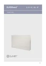
Страница 45: ...ELFORoom2 3 5 11 15 17 Water terminal 45 ...

Страница 46: ...ny is to offer advanced systems that assure the best com fort reduce the energy con sumption the installation and maintenance costs for all the life cycle of the system With this manual we want to give you information that are useful in all the phases from the reception to the installation and use until the disposal so that a system so advanced offers the best procedure of installation and use Bes...

Страница 47: ...INDEX 1 2 3 4 General 48 Reception 51 Positioning 52 Water connections 55 Electrical connections 60 Control 67 Maintenance 78 Decommissioning 81 Technical data 82 Residual risks 86 5 6 7 8 9 10 47 ...

Страница 48: ...All unit modifications will end the warranty coverage and the manufacturer responsibility Breakdown Malfuction Disable the unit immediately in case of breakdown or malfunction Contact a constructor certified assistance service Use original spares parts only User training The installer has to train the user on start up shutdown set points change standby mode maintenance what to do what not to do in...

Страница 49: ...idden to dispose of or leave in the reach of children the packaging materials which could become a source of danger It is forbidden to climb onto the appliance or rest any object on it The external parts of the appliance can reach temperatures of more than 70 C DANGER FROM BURNS TAKE CARE WHEN TOUCHING 1 4 FUNDAMENTAL SAFETY RULES 1 5 UNIT INDENTIFICATION Serial number label The serial number labe...

Страница 50: ...vailable only with options 3V010 HIDE2X Remote control with E I 3V on off for wall installation available only with options 3V010 HIDE3X Plurifunctional remote control for wall installation available only with options 3V010 HID T2X HID T2 electronic ambient control external temperature only HID T3X HID T3 electronic ambient control external temperature and humidity HID TI2X HID TI2 flush mounted e...

Страница 51: ...al in conformity with local regulations 2 1 PRELIMINARY INFORMATION 2 RECEPTION 2 2 DELIVERY CONTROL 2 3 HANDLING Do not tramble Do not handle the unit alone Do not leave loose packages during the transport Before accepting the delivery you have to check That the unit hasn t been damaged during tran sport Check that the materials delivered correspond with that indicated on the transport document c...

Страница 52: ...ct all functional spaces indicated in the figure Avoid installing the unit in proximity to positions subject to exposure to direct sunlight in proximity to sources of heat in damp areas or places with probable contact with water in places with oil fumes places subject to high frequencies Make sure that the wall on which the unit is to be installed is strong enough to support the weight the part of...

Страница 53: ...s fig 3 1 ref C one on each side Make sure that there is sufficient inclination of the unit towards the drainage pipe to facilitate the water drainage fig 3 1 ref D Fully tighten all 6 fixing screws 3 5 SIDE OPENING 3 POSITIONING The following descriptions of the various mounting phase and the relative designs refer to a version of the machine with fixtures on the left The operations for the mount...

Страница 54: ...2 Use a suitable drill to make the holes with and insert the toggle bolts 2 for each bracket fig 3 3 ref A fix the two brackets fig 3 3 ref B Do not over tighten the screws so that the brackets can be adjusted with a spirit level fig 3 4 Fully tighten the four screws to block the two brackets Check the stability by manually moving the brackets to the right and to the left up and down Mount the uni...

Страница 55: ...ectly to the discharge tray positioned at the bottom of the side shoulder underneath the hydraulic fixtures In a horizontal installation the discharge tube is connected to the one already present on the machine If possible make the condensation liquid flow directly in a gutter or a rainwater discharge When discharging directly into the main drains it is advisable to make a siphon to prevent bad sm...

Страница 56: ...te carefully the inflow and outflow pipes up to the machine union to prevent any drops of condensation outside the same collection bowl insulate the bowl condensation discharge pipe along all of its length 4 4 FIXTURE ROTATION The operations described and the relative images refer to a machine with fixtures on the left on which the fixtures on the right side must be rotated If there is a machine a...

Страница 57: ...e electrical connections Remove the cables inside the machine and re insert them from the opposite side For the motor connection use the special cable for right hand fixtures available as an accessory Invert the mounting positions of the door fig 4 6 ref A with the control panel fig 4 6 ref C and remount them in their respective positions Dismount the condensation collection tray fig 4 6 ref F and...

Страница 58: ...fixing screw fig 4 7 rif G move the tray and rest it on the opposite side so that the fixture mouth for the dripcollector extension comes out of the structure and block the tray with the screw previously removed re insert the drip collector extension and the plug on the opposite side rotate the exchanger moving the fixtures to the opposite side and reinsert it on the machine tighten all the fixing...

Страница 59: ...alves of the appliance close them and continue filling until reaching the nominal value for the system Check the hydraulic seal of the gaskets It is advisable to repeat these operations after the appliance has been running for a few hours and periodically check the pressure of the system open the front grill and completely unscrew the fixing screws on the springs fig 4 8 rif B fix the two clamps b...

Страница 60: ...erial number label 5 2 ELECTRICAL DATA 5 3 CONNECTIONS 1 Refer to the unit electrical diagram the number of the diagram is shown on the serial number label 2 Verify that the network has characteristics conforming to the data shown on the serial number label 3 Before starting work verify that the sectioning device at the start of the unit power line is open blocked and equip ped with cartel warning...

Страница 61: ...contact max 1A CHILLER Cooling go ahead output chiller free contact max 1A SW2 Remote ON OFF H2 Water temperature probe 4T heating 2T cooling heating H4 Water temperature probe 4T cooling S1 Grill safety micro switch Y1 Water solenoid valve 4T heating 2T heating cooling Y2 Water solenoid valve 4T cooling 4 tube Y1 Y2 2 tube Y1 61 ...

Страница 62: ... free contact max 1A CHILLER Cooling go ahead output chiller free contact max 1A SW2 Remote ON OFF H2 Water temperature probe 4T heating 2T cooling heating H4 Water temperature probe 4T cooling S1 Grill safety micro switch Off switched off ventilation at setpoint satisfied Y1 Water solenoid valve 4T heating 2T heating cooling Y2 Water solenoid valve 4T cooling Radiant option see 5 6 62 ...

Страница 63: ...n 1 Bus RS485 2 ELFOControl Home 3 GAIA 4 ELFOFRESH2 5 Zone with 2 ELFOROOM2 with keypad and HID Ti2 thermostat controls both terminals 6 Zone with 1 ELFOROOM2 with keypad and HID Ti2 thermostat that controls the terminal 7 ELFOROOM2 with keypad and HID T3 thermostat that controls both terminals 8 ELFOROOM2 with built in thermostat 63 ...

Страница 64: ...5 ELECTRICAL CONNECTIONS 5 10 Connection with 4 speed electronic control AIR Air temperature probe H2 Water temperature probe S1 Grill safety micro switch Y1 Water solenoid valve 2 PIPE SYSTEM 64 ...

Страница 65: ...5 ELECTRICAL CONNECTIONS HID E2 thermostat 4 pipe system HID E2 thermostat 2 pipe system 5 11 Thermostats connections Command enable 3 speed HID E1 thermostat 2 pipe system 65 ...

Страница 66: ...CTRICAL CONNECTIONS 0 10V enable command 10v fan 1400 rpm 1v fan 450 rpm 1v fan off HID E3 thermostat 4 pipe system H2O water temperature probe HID E3 thermostat 2 pipe system H2O water temperature probe 66 ...

Страница 67: ...nd hot water solenoid valves are activated temperature change set Use the two buttons to set the desired room temperature which is displayed on the 3 digit display The adjustment range is from 16 to 28 C with resolution is 0 5 C but are also permitted off scale values of 5 C and 40 C Only set these values for short periods and then set the selection to an intermediate value The command is very pre...

Страница 68: ...ooling turn on In heating mode the symbol is ON with setpoint higher than the room temperature both OFF with lower setpoint In cooling mode the symbol is ON with setpoint lower than the room temperature both OFF higher with setpoint In the versions with 4 pipes with the automatic heating cooling adjustment on if the 2 symbols turn on simultaneously this means that the setpoint has been reached neu...

Страница 69: ...sly To return again to the manual cooling only or heating only condition press the sum win button ref A for 10 seconds until of the cooling symbols ref C and heating ref B switch off Press the button again to select the winter function Check the functioning of the heating symbol ref B alight when the setpoint is higher than the room temperature both switched off when the setpoint is lower Press th...

Страница 70: ...ols are on when the setpoint is lower than the ambient temperature and off when the setpoint is higher Stand by keep the mode off button pressed for about 2 seconds The lack of a warning light indicates the stand by status no function mode off Start up shutdown The control makes the control of the ambient temperature fully autonomous by setting the setpoint that can be adjusted from 5 to 40 C one ...

Страница 71: ...t not met above 20 C in cooling mode below 30 C in heating mode The LED of the selected function flashes and the fan is stopped until the water temperature reaches a value that is suitable to meet the request Alarms mode off Fan speed adjustment Pressing the mode off button changes the fan speed between supersilent minimum medium and maximum When the function is activated the relative symbol on th...

Страница 72: ...han 5 minutes the error is displayed and the ventilation radiator fan coil is disabled flashes three pause Blocked as the water is not suitable unlocked automatically after 45 minutes or manually by pressing the ON stand by key twice flashes four pause Water probe malfunction all the outputs are turned off until the problem is solved flashes five pause The warning is associated with a fan motor pr...

Страница 73: ...ic In the ON position the ventilation is inhibited thus letting the machine heat the room through natural radiation or convection as happens with traditional radiators in the OFF position the fan functions normally Set cursor B to ON in cooling only to enable the continual ventilation at the minimum speed even after the set point has been reached in the neutral band to ensure a more regular functi...

Страница 74: ...ers t a 21 0 REMOTE ECO AUTO E c o S w in g Display room humidity ONLY FOR HID T3 THERMOSTAT WITH UR PROBE Hold down on both arrows of the SET key the room temperature is displayed alternating with the letters t a Hold down the Set key and the humidity value will appear alternating with the letters ur 21 0 REMOTE ECO AUTO E c o S w in g Go from HEATING mode to COOLING mode and vice versa If the un...

Страница 75: ...to deactivate it When silent mode is activated the thermostat display shows the letters SIL When the Set changing keys are pressed the first pressing displays the actual set instead of SIL After 10 sec time out SIL is visualized if no keys that modify the set point are pressed If the function is managed remotely via ModBus no modification can be performed the word REMOTE starts flashing 21 0 REMOT...

Страница 76: ...will show the message Fan and the bar of the fans press key again the display will show only the message tA press the key OK to confirm the selection The message tA will flash on the display followed by a return to normal operation in which the message tA will alternate with the ambient temperature for a few seconds You can also go back to normal operation by pressing instead of the key OK the key...

Страница 77: ...de When setting fan speed you will go from AUTOMATIC where the speed of the fans is controlled automatically based on ambient temperature to MANUAL operation where the user sets the speed To go back to automatic fan operation repeatedly press until the entire bar is flashing Manual status of the fans is indicated by a flashing bar The setting of fan speeds is not cyclical Silenced mode To activate...

Страница 78: ...ions with aspiration Insert your hands under the end of mobile panel Press the plastic lug B Lift and extract the mobile panel C Extract the filter D 7 5 Extraction of filter cells in the versions with mobile aspiration panel Suck up the powder with a vacuum cleaner rif A Wash the filter ref B with running water without using detergents or solvents and leave to dry Remount the filter on the cooler...

Страница 79: ...ig 7 5 ref A into the special slots fig 7 5 ref B turn it and hook it up with a slight tap on the upper part For the versions with a mobile panel rest it in its position parallel to the front panel and press until it is blocked 7 7 Ending clearing operations fig 7 4 fig 7 5 79 ...

Страница 80: ...aks in the hydraulic connections of the system Check the leak and fully tighten the connections Leaks in the valve unit Check the state of the gaskets There are formations of dew on the front panel The thermostatic valve built into the connection unit between plate and battery does not close the flow towards the wall Replace the union that joins the thermostatic valve to the water inlet upper unit...

Страница 81: ...EC on waste electrical and electronic equipment WEEE The potential effects on the environment and on human health due to the presence of hazardous substances are shown in the use and maintenance manual in the section on residual risks Information in addition to that indicated below if required can be obtained from the manufacturer distributor importer who are responsible for the collection handlin...

Страница 82: ...RGE DUCT Ø 14 MM SIZE 3 5 11 15 17 A mm 737 937 1137 1337 B mm 131 131 131 131 C mm 579 579 579 579 Net weight kg 17 20 23 26 1537 131 579 29 Built in version 2 pipes Cased version 2 pipes SIZE 3 5 11 15 17 A mm 527 727 927 1227 B mm 126 126 126 126 C mm 579 579 579 579 Net weight kg 9 12 15 18 1327 126 579 21 A B 1 2 3 C 1 2 3 A B C 82 ...

Страница 83: ...RGE DUCT Ø 14 MM SIZE 3 5 11 15 17 A mm 737 937 1137 1337 B mm 131 131 131 131 C mm 639 639 639 639 Net weight kg 17 20 23 26 1537 131 639 29 Built in version 4 pipes Cased version 4 pipes SIZE 3 5 11 15 17 A mm 527 727 927 1227 B mm 126 126 126 126 C mm 639 639 639 639 Net weight kg 9 12 15 18 1327 126 639 21 A B 1 2 3 C 1 2 3 A B C 83 ...

Страница 84: ... 50 230 1 50 230 1 50 230 1 50 1 Ambient temperature 27 C 19 5 WB water inlet 7 C and outlet 12 C 2 Ambient temperature 27 C 19 5 WB water inlet 7 C and outlet 12 C 3 Ambient temperature 20 C DB water inlet 45 C and outlet 40 C 4 TGZ tangential 5 Air flow at max speed measured with clean filters Size 3 5 11 15 17 F L A FULL LOAD CURRENT AT MAX ADMISSIBLE CONDITIONS F L A Total A 0 11 0 16 0 18 0 2...

Страница 85: ...0 dB A dB A 3 51 51 47 49 48 43 37 27 39 52 5 45 45 48 50 51 45 38 28 40 53 11 51 51 48 49 50 45 38 28 39 53 15 47 47 49 48 51 44 37 28 39 53 17 52 52 50 49 52 45 39 29 43 54 Sound power level FAN SPEED Low speed L Size Sound Power Level dB Sound pressure level Octave band Hz 63 125 250 500 1000 2000 4000 8000 dB A dB A 3 49 49 34 33 27 22 22 23 23 36 5 45 45 39 39 22 27 23 23 26 40 11 46 46 39 41...

Страница 86: ...amge to persons things or the unit itself Always contact the qualified assistance centre Failing to close the unit panels or failure to check the correct tightening of all of the panelling fixing screws may cause damage to persons things or the unit itself Periodically check that all of the panels are correctly closed and fixed If there is a fire the temperature of the refrigerant could reach valu...

Страница 87: ...NOTES 87 ...

Страница 88: ...NOTES 88 ...

Страница 89: ...ELFORoom2 3 5 11 15 17 Terminal à eau 89 ...

Страница 90: ...e l entreprise c est d offrir aux clients des systèmes évolués qui assurent le meilleur confort qui réduisent les consom mations d énergie les coûts d installation et d entretien pour tout le cycle de vie du système Par ce manuel nous désirons fournir des informations qui pourront être utiles en toutes les phases de la réception à l installation à l utilisation jusqu à l élimination afin que un sy...

Страница 91: ...Generalite 92 Réception 95 Positionnement 96 Raccordements hydrauliques 99 Raccordements electriques 104 Reglage 111 Entretien 122 Mise hors service 125 Informations techniques 126 Risques résiduels 130 5 6 7 8 9 10 91 ...

Страница 92: ...responsabilité avec annulation de la garantie en cas de quelconque modification Panne ou fonctionnement défectueux Désactiver immédiatement l unité en cas de panne ou mauvais fonctionnement S adresser à un centre d assistance technique agréé Demander l utilisation de pièces de rechange originales Formation utilisateur L installateur doit instruire l utilisateur en particulier sur allumage arrêt mo...

Страница 93: ... laisser à la portée des enfants le matériel d emballage car il peut être une source potentielle de danger Il est défendu de monter avec les pieds sur l appareil et ou d y poser quelque objet que ce soit L appareil peut atteindre des températures sur les com posants externes supérieures à 70 C FAIRE TRES ATTENTION AU CONTACT DANGER DE BRULURES 1 4 REGLES FONDAMENTALES DE SECURITE 1 5 IDENTIFICATIO...

Страница 94: ...les options 3V010 HIDE2X Contrôle ambiant simplifié E H 3V on off pour installation murale disponible seulement avec les options 3V010 HIDE3X Contrôle ambiant plurifonctionnel pour installation à mur disponible seulement avec les options 3V010 HID T2X Contrôle ambiant électronique HID T2 externe seulement température HID T3X Contrôle ambiant électronique HID T3 externe température et humidité HID ...

Страница 95: ...t attention à ne pas endommager l unité Recycler et éliminer le matériel d emballage conformément aux normes locales 2 1 INFORMATIONS PRÉLIMINAIRES 2 RÉCEPTION Avant d accepter la livraison contrôler que l unité n a pas subi de dommages pendant le trans port que le matériel délivré correspond à ce qu est indiqué sur le document de transport en comparant les données avec l étiquette de matricule po...

Страница 96: ...xposées Respecter les espaces fonctionnels indiqués dans figure Eviter l installation de l unité à proximité de positions soumises à l exposition directe aux rayons solaires à proximité de sources de chaleur dans des endroits humides ou des zones de contact probable avec l eau dans des locaux présentant des vapeurs d huile dans des locaux soumis à des hautes fréquences S assurer que le mur sur leq...

Страница 97: ...une inclinaison appropriée de l appareil vers le tube de drainage pour faciliter la sortie de l eau fig 3 1 rif D Serrer définitivement les 6 vis de fixation 3 5 OUVERTURE FLANCS 3 POSITIONNEMENT Les descriptions suivantes sur les différentes phases de montage et les dessins correspondants se réfèrent à une version de la machine ayant les prises à gauche Les descriptions pour les opérations de mon...

Страница 98: ...r avec un foret approprié et insérer les chevilles 2 par étrier fig 3 3 réf A fixer les deux étriers fig 3 3 réf B Ne pas trop serrer les vis de façon à pouvoir effectuer un réglage des étriers avec un niveau fig 3 4 Bloquer définitivement les deux étriers en serrant complètement les quatre vis En vérifier la stabilité en déplaçant manuellement les étriers vers la droite et vers la gauche le haut ...

Страница 99: ...se branche directement au bas d évacuation placé en bas sur le montant latéral sous les prises hydrauliques Dans l installation horizontale le tube d évacuation est branché au tube déjà présent sur la machine Si possible faire s écouler les condensats directement dans une gouttière ou dans une évacuation d eaux blanches En cas d évacuation vers le tout à l égout il est conseillé de réaliser un sip...

Страница 100: ...es tubes de refoulement et de retour jusqu à l entrée de la machine de façon à empêcher les égoutte ments de condensats à l extérieur du bac de récupération isoler le tube d évacuation des condensats du bac sur toute sa longueur 4 4 ROTATION DES FIXATIONS Les opérations décrites et les images correspondantes se rapportent à une machine avec les prises à gauche sur la quelle les prises doivent tour...

Страница 101: ...es branchements électriques Enlever les câblages à l intérieur de la machine et les remettre en place du côté opposé Utiliser pour la connexion du moteur le câblage pour fixations à droite disponible comme accessoire Inverser les positions de montage du portillon fig 4 6 réf A avec le panneau de commande fig 4 6 réf C et les remonter dans leurs positions respectives Démonter le bac de récupération...

Страница 102: ...récupération des condensats fig 4 7 réf G amener le bac en appui sur le côté opposé de telle sorte que le raccord de prise pour la rallonge brise goutte sorte puis bloquer le bac au moyen de la vis précédemment enlevée remettre en place la rallonge brise goutte et du côté oppo sé le bouchon tourner l échangeur en portant les prises du côté opposé et le remettre en place sur la machine visser toute...

Страница 103: ...tion de l appareil manuels ou automatiques Commencer le remplissage en ouvrant lentement le robi net de remplissage en eau de l appareil Pour les modales installés en position verticale agir au moyen d un tournevis sur l évent de la batterie situé plus haut fig 4 9 réf A pour les appareils installés en position horizontale agir sur l évent situé plus haut fig 4 9 réf B Quand il commence à sortir d...

Страница 104: ...nuel se référent à l unité standard accessoires exclus Se référer donc aux données électriques indiquées sur l étiquette de matricule 5 2 DONNEES ELECTRIQUES 5 3 RACCORDEMENTS 1 se référer au schéma électrique de l unité le numéro de schéma électrique est indiqué dans l étiquette de matricule 2 vérifier que le réseau ait caractéristiques conformes aux données indiquées sur l étiquette de matricule...

Страница 105: ...tement Refroidissement chiller contact propre maxi 1A SW2 On Off à distance H2 capteur de température eau 4T Chauffage 2T Refroidissement Chauffage H4 capteur de température eau 4T Refroidissement S1 micro interrupteur de sécurité grille Y1 électrovalve eau 4T Chauffage 2T Chauffage Refroidissement Y2 électrovalve eau 4T Refroidissement 4 tubes Y1 Y2 2 tubes Y1 105 ...

Страница 106: ...ER sortie consentement Refroidissement chiller contact propre maxi 1A SW2 On Off à distance H2 capteur de température eau 4T Chauffage 2T Refroidissement Chauffage H4 capteur de température eau 4T Refroidissement S1 micro interrupteur de sécurité grille off ventilation éteinte à point de consigne satisfaite Y1 électrovalve eau 4T Chauffage 2T Chauffage Refroidissement Y2 électrovalve eau 4T Refroi...

Страница 107: ...at HID Ti2 qui contrôle touts les deux les terminaux 6 zone avec 1 ELFOROOM2 avec clavier et thermostat HID Ti2 qui contrôle le terminal 7 ELFOROOM2 avec clavier et thermostat HID T3 qui contrôle touts les deux les terminaux 8 ELFOROOM2 avec thermostat à bord 5 8 MINI RÉSEAU MAX 9 ELFORoom2 Résistance terminaison de réseau 120 Ω à la charge du client 107 ...

Страница 108: ... ELECTRIQUES 5 10 Raccordement avec contrôle électronique à 4 vitesses AIR capteur de température air H2 capteur de température eau S1 micro interrupteur de sécurité grille Y1 électrovalve eau INSTALLATION 2 TUBES 108 ...

Страница 109: ...CORDEMENTS ELECTRIQUES Thermostat HID E2 installation 4 tubes Thermostat HID E2 installation 2 tubes 5 11 Raccordements thermostats Activer la commande à 3 vitesses Thermostat HID E1 installation 2 tubes 109 ...

Страница 110: ...CTRIQUES Activer la commande 0 10V 10v fan 1400 rpm 1v fan 450 rpm 1v fan off Thermostat HID E3 installation 4 tubes H2O capteur de température eau Thermostat HID E3 installation 2 tubes H2O capteur de température eau 110 ...

Страница 111: ...ssous de 5 C les sorties électrovalve eau chaude et consentement chaudière sont activées modifier la température réglée Paramétrer à l aide des deux touches la valeur de température souhaitée dans la pièce affichée sur 3 chiffres sur l écran La plage de réglage va de 16 à 28 C la résolution est de 0 5 C sont permises hors échelle des valeurs de 5 C et 40 C Paramétrer ces valeurs uniquement pour de...

Страница 112: ...allumage des 2 symboles de chauffage actif ou rafraichissement actif En mode chauffage le symbole est allumé avec une valeur de consigne supérieure à la température ambiante sont tous les deux éteints avec une valeur de consigne inférieure En mode rafraîchissement le symbole est allumé avec une valeur de consigne inférieure à la température ambiante sont tous les deux éteints avec une valeur de co...

Страница 113: ... de nouveau au réglage du fonctionnement refroidissement seul et chauffage seul manuel appuyer sur la touche été hiv réf A pendant 10 secondes jusqu à l extinction des symboles refroidissement réf C et chauffage réf B Appuyer de nouveau sur la touche pour sélectionner la fonction hiver Vérifier le fonctionnement du symbole de chauffage réf B allumée avec valeur de consigne supérieure à la températ...

Страница 114: ...ne est inférieur à la température ambiante éteints lorsque le point de consigne est supérieur Veille garder enfoncée la touche ON veille pendant environ 2 secondes L absence de toute indication lumineuse identifie l état de veille absence de fonction mode off Allumage arrêt La commande rend complètement autonome le réglage de la température ambiante à travers la configuration du point de consigne ...

Страница 115: ...froidissement en dessous des 30 C en chauffage La LED de la fonction sélectionnée clignote et le ventilateur est arrêté tant que la température de l eau n atteint pas une valeur adéquate pour répondre aux exigences alarmes mode off réglage vitesse de ventilation A chaque pression du bouton mode off correspond la variation de la vitesse du ventilateur entre supesilent minimale moyenne et maximale L...

Страница 116: ...reur est affichée et le ventilo radiateur ventilo convecteur est désactivé 3 clignotements pause Bloqué pour eau non adéquate Le déblocage est effectué automatiquement après 45 minutes ou bien manuellement en appuyant deux fois sur la touche ON stand by 4 clignotements pause Dysfonctionnement de la sonde à eau toutes les sorties sont éteintes jusqu à la résolution du problème 5 clignotements pause...

Страница 117: ...n a par contre le fonctionnement normal du ventilateur En plaçant le curseur B sur ON l on active uniquement en refroidissement la ventilation continue à la vitesse minimum même une fois que la valeur de consigne a été atteinte dans la bande neutre pour permettre un fonctionnement plus régulier du capteur de température Le passage à la condition de chauffage annule la condition avec le curseur en ...

Страница 118: ...SET la température ambiante s affiche en alternance au sigle t a 21 0 REMOTE ECO AUTO E c o S w in g Visualiser l humidité ambiante UNIQUEMENT POUR THERMOSTATS HID T3 AVEC SONDE UR Appuyer longtemps sur les deux flèches de la touche SET la température ambiante s affiche en alternance au sigle t a Appuyer encore longtemps sur la touche set et apparaîtra la valeur d humidité alternée au message ur 2...

Страница 119: ...e sur l écran du thermostat apparaît le message SIL Lorsque sont enfoncées les touches de variation du Réglage la première pression affiche le réglage courant au lieu du message SIL Après 10 sec si aucune touche de variation de la valeur de réglage n est enfoncée apparaît le message SIL Si la fonction est gérée à distance via ModBus il n est pas possible d effectuer des modifications le libellé RE...

Страница 120: ... écran apparaît le message Fan et la barre des ventilateurs appuyer de nouveau sur la touche sur l écran apparaît uniquement le message tA appuyer sur la touche OK pour confirmer le choix sur l écran clignotera le message tA pour ensuite retourner au fonctionnement normal et pendant quelques secondes le message tA sera alterné à la valeur de la température ambiante Il est aussi possible de retourn...

Страница 121: ...te à un fonctionnement MANUEL où la vitesse est définie par l utilisateur Pour passer de nouveau au fonctionnement automatique de la ventilation appuyer de manière répétée jusqu à ce qu apparaisse toute la barre clignotante L état manuel des ventilateurs est indiqué par une barre clignotante La programmation de la vitesse des ventilateurs n est pas de type circulaire Modalité silence Pour activer ...

Страница 122: ... un chiffon doux et humecté d eau Ne pas utiliser d éponges abrasives ou corrosives pour ne pas abîmer les surfaces peintes enlever la grille avant en la soulevant légèrement fig 7 1 réf A et la faire tourner jusqu à ce qu elle sorte complètement de son logement fig 7 1 rif B enlever le filtre fig 7 1 réf C en tirant dans le sens horizontal vers l extérieur fig 7 1 rif D 7 4 Enlèvement des cellule...

Страница 123: ...es fentes prévues à cet effet fig 33 réf B les faire tourner et les accrocher avec un léger coup dans la partie supérieure Pour les versions à panneau mobile le poser dans sa position parallèlement à la façade et appuyer de façon à le bloquer 7 7 Fin des opérations de nettoyage fig 7 4 fig 7 5 123 ...

Страница 124: ...u circuit Contrôler la fuite et serrer à fond les branchements Pertes dans le groupe valves Vérifier l état des joints Des formations de buée sont présentes sur le panneau frontal La valve thermostatique intégrée dans le groupe de branchement entre plaque et batterie ne ferme pas le flux vers la paroi Remplacer le raccord intégrant la valve thermostatique dans le groupe supérieur d entrée d eau Is...

Страница 125: ... et électroniques DEEE Les effets potentiels sur l environnement et sur la santé humaine en raison de la présence de substances dangereuses sont reportés dans le manuel d emploi et de maintenance à la section sur les risques résiduels Des informations supplémentaires à celles indiquées ci dessous au besoin peuvent être demandées soit au fabricant distributeur importateur qui sont responsables de l...

Страница 126: ...ATS Ø 14 MM TAILLES 3 5 11 15 17 A mm 737 937 1137 1337 B mm 131 131 131 131 C mm 579 579 579 579 Poids net kg 17 20 23 26 1537 131 579 29 Version à encastrer 2 tubes TAILLES 3 5 11 15 17 A mm 527 727 927 1127 B mm 126 126 126 126 C mm 579 579 579 579 Poids net kg 9 12 15 18 1327 126 579 21 Version apparente 2 tubes A B 1 2 3 C 1 2 3 A B C 126 ...

Страница 127: ...ATS Ø 14 MM TAILLES 3 5 11 15 17 A mm 737 937 1137 1337 B mm 131 131 131 131 C mm 639 639 639 639 Poids net kg 17 20 23 26 1537 131 639 29 Version à encastrer 4 tubes TAILLES 3 5 11 15 17 A mm 527 727 927 1227 B mm 126 126 126 126 C mm 639 639 639 639 Poids net kg 9 12 15 18 1327 126 639 21 Version apparente 4 tubes A B 1 2 3 C 1 2 3 A B C 127 ...

Страница 128: ...V 230 1 50 230 1 50 230 1 50 230 1 50 230 1 50 1 Air ambiant à 27 C 19 5 BH eau entrée 7 C et sortie à 12 C 2 Air ambiant à 27 C 19 5 BH eau entrée 7 C et sortie à 12 C 3 Air ambiant à 20 C BS eau entrée 45 C et sortie à 40 C 4 TGZ tangentiel 5 Débit d air à la vitesse maximum mesurée avec des filtres propres LIMITES DE FONCTIONNEMENT REFROIDISSEMENT Tailles 3 5 11 15 17 ÉCHANGEUR EXTERNE SOURCE T...

Страница 129: ...00 dB A dB A 3 51 51 47 49 48 43 37 27 39 52 5 45 45 48 50 51 45 38 28 40 53 11 51 51 48 49 50 45 38 28 39 53 15 47 47 49 48 51 44 37 28 39 53 17 52 52 50 49 52 45 39 29 43 54 Niveau de puissance sonore VITESSE VENTILATEUR Faible vitesse L Tailles Niveaux Sonores dB Niveau de pression sonore Bande d octave Hz 63 125 250 500 1000 2000 4000 8000 dB A dB A 3 49 49 34 33 27 22 22 23 23 36 5 45 45 39 3...

Страница 130: ...tuées par du personnel non qualifié peuvent être à l origine de dommages pour les personnes les biens ou l unité Contacter toujours un centre d assistance qualifié La non fermeture des panneaux de l unité ou l absence de vérification du serrage de toutes les vis de fixation des panneautages peuvent être à l origine de dommages pour les personnes les biens ou l unité Vérifier périodiquement la ferm...

Страница 131: ...NOTE 131 ...

Страница 132: ...NOTE 132 ...

Страница 133: ...ELFORoom2 3 5 11 15 17 Terminal de agua 133 ...

Страница 134: ...na alta fiabilidad eficiencia calidad y seguridad El objetivo de la compañía es a portar a sus clientes sistemas avanzados que ofrecen el mejor confort redu cen los consumos de energía los costes de instalación y mantenimiento para el ciclo de vida completo del sistema Con este manual queremos ofrecer informaciónes útiles en todas las fases recepción instalación uso y hasta la disposición a fin de...

Страница 135: ...eralidades 136 Recepción 139 Colocación 140 Conexiones hidráulicas 143 Conexiones eléctricas 148 Regulación 155 Mantenimiento 166 Cesión de la unidad 169 Informaciónes técnicas 170 Riesgos residuales 174 5 6 7 8 9 10 135 ...

Страница 136: ...éctrica de la unidad Modificaciónes Cualquier tipo de modificación inválida la garantía y la respon sabilidad del fabricante Averías o malfuncionamiento En caso de averías o malfuncionamiento apagar la unidad Recurrir a un centro de asistencia autorizado por el fabricante Exigir el uso de piezas de recambio originales Formacoión del usuario El instalador debe instruir al usuario especialmente acer...

Страница 137: ...stituir una fuente de peligro Está prohibido subir con los pies sobre el aparato y o apoda sobre el mismo cualquier tipo de objeto Los componentes externos del aparato pueden alcanzar temperaturas superiores a 70 C PRESTE LA MÁXIMA ATENCIÓN PARA EVITAR EL PELIGRO DE QUEMADURAS 1 4 REGLAS FUNDAMENTALES DE SEGURIDAD 1 5 IDENTIFICACIÓN DE LA UNIDAD Placa de serie La placa de serie permite identificar...

Страница 138: ...alación a pared sólo con las opciones 3V010 HIDE2X Control ambiente semplificado E l 3V on off para instalación a pared sólo con las opciones 3V010 HIDE3X Control ambiente multifunción para instalación a pared sólo con las opciones 3V010 HID T2X Control ambiente electrónico HID T2 externo sólo temperatura HID T3X Contol ambiente electrónico HID T3 externo temperatura y humedad HID TI2X Control amb...

Страница 139: ...l centro de la unidad Antes de iniciar el traslado asegurarse que la unidad está en equilibrio estable Eliminación embalaje Tenir cuidado de no dañar la unidad Reciclar y eliminar el material de embalaje de acuerdo a las normativas locales 2 1 INFORMACIÓNES PRELIMINARES Antes de aceptar la entrega comprobar Que no se hayan producido daños en el transporte Que el material entregado corresponde a lo...

Страница 140: ...spacios funcionales que se muestran en la figura Evite la instalación de la unidad en lugares expuestos directamente a los rayos solares cerca de fuentes de calor ambientes húmedos y zonas con probable contacto con el agua ambientes con vapores de aceite ambientes expuestos a altas frecuencias Verifique que la pared en la que se desea instalar la unidad tenga una estructura y una capacidad adecuad...

Страница 141: ...de fijación y de los dos tornillos posteriores Perfore con una punta adecuada e introduzca los tacos 2 para cada estribo Fig 3 1 Ref A fije los dos estribos Fig 3 1 Ref B No apriete excesivamente los tornillos Coloque la máquina en los dos estribos y fije los dos tornillos en los tacos posteriores Fig 3 1 Ref C uno de cada lado Se recomienda dar una adecuada inclinación de la unidad hacia el tubo ...

Страница 142: ...ore con una punta adecuada e introduzca los tacos 2 para cada estribo Fig 3 3 Ref A fije los dos estribos Fig 3 3 Ref B No apriete excesivamente los tornillos para poder regular los estribos con un nivel de burbuja Fig 3 4 Bloquee definitivamente los dos estribos apretando completamente los cuatro tornillos Verifique la estabilidad desplazando manualmente los estribos en sentido lateral y vertical...

Страница 143: ...nferior al 1 En la instalación vertical el tubo de descarga se conecta directamente a la cubeta de descarga colocada en la parte inferior en el pilar lateral debajo de las conexiones hidráulicas En la instalación horizontal el tubo de descarga se conecta al tubo presente en la máquina Si es posible haga fluir el líquido de condensación directamente hacia un canalón o hacia una descarga de aguas bl...

Страница 144: ...y retorno hasta la embocadura de la máquina para impedir el goteo de condensación fuera de la cubeta colectora aísle el tubo de descarga de la condensación de la cubeta en toda su longitud 4 4 ROTACIÓN EMPALMES Las operaciones descritas y las imágenes correspondientes se refieren a una máquina con las conexiones a la izquierda en la que se requiere la rotación de las conexiones hacia el lado derec...

Страница 145: ...ectores de las conexiones eléctricas Extraiga los cables de la máquina e introdúzcalos por el lado opuesto Para conectar el motor utilice el específico cableado de conexión que se encuentra a la derecha disponible como accesorio Invierta la posición de montaje de la puerta Fig 4 6 Ref A y el panel de mando Fig 4 6 Ref C y remóntelos en la nueva posición Desmonte la cubeta colectora de condensación...

Страница 146: ...e la cubeta colectora de condensación central Fig 4 7 Ref G apóyela en el lado opuesto de tal modo que de la estructura sobresalga la boca de empalme para la alargadera rompegotas y fíjela con el tornillo previamente desenroscado Reintroduzca la alargadera rompegotas y en el lado opuesto el tapón Gire el intercambiador llevando las conexiones al lado opuesto y colóquelo nuevamente en la máquina En...

Страница 147: ...tomáticos Inicie el llenado abriendo lentamente el grifo de carga de agua de la instalación Para los modelos instalados en posición vertical accione con un destornillador el aliviadero de la batería situado más arriba Fig 4 9 Ref A para los aparatos instalados en posición horizontal accione el aliviadero situado más arriba Fig 4 9 Ref B Cuando comienza a salir agua a través de las válvulas de purg...

Страница 148: ...as normas de seguridad vigentes 5 1 INFORMACIÓNES PRELIMINARES La placa de serie contiene los datos eléctricos especificos de la unidad incluidos los eventuales accesorios eléctricos Los datos eléctricos indicados en el boletín técnico y en el manual se refieren a la unidad estándar accesorios no incluidos Referirse a los datos indicados en la placa de serie 5 2 DATOS ELÉCTRICOS 5 3 CONEXIONES 1 C...

Страница 149: ...a consentimiento enfriamiento chiller contacto libre máx 1 A SW2 ON OFF remoto H2 sonda temperatura agua 4T calefacción 2T enfriamiento calefacción H4 sonda temperatura agua 4T enfriamiento S1 microinterruptor seguridad Y1 electroválvula agua 4T calefacción 2T calefacción enfriamiento Y2 electroválvula agua 4T enfriamiento 4 tubos Y1 Y2 2 tubos Y1 149 ...

Страница 150: ...dera contacto libre máx 1 A CHILLER salida consentimiento enfriamiento chiller contacto libre máx 1 A SW2 ON OFF remoto H2 sonda temperatura agua 4T calefacción 2T enfriamiento calefacción H4 sonda temperatura agua 4T enfriamiento S1 microinterruptor seguridad off ventilazione spenta a setpoint soddisfatto Y1 electroválvula agua 4T calefacción 2T calefacción enfriamiento Y2 electroválvula agua 4T ...

Страница 151: ...ue comanda ambos terminales 6 zona con 1 ELFOROOM2 con teclado y termostato HID Ti2 que comanda el terminal 7 ELFOROOM2 con teclado y termostato HID T3 que comanda ambos terminales 8 ELFOROOM2 con termostato a bordo Resistencia terminación de red 120 Ω a carga del cliente 5 8 MINI RED MAX 9 ELFORoom2 5 9 ELFOSystem GAIA Edition 151 ...

Страница 152: ...ONEXIONES ELÉCTRICAS 5 10 Conexión con control electrónico 4 velocidades AIR sonda temperatura aire H2 sonda temperatura agua S1 microinterruptor seguridad Y1 electroválvula agua INSTALACIÓN A 2 TUBOS 152 ...

Страница 153: ...ONEXIONES ELÉCTRICAS Termostato HID E2 instalación a 4 tubos Termostato HID E2 instalación a 2 tubos 5 11 Conexiónes termostatos Habilitar comando 3 velocidades Termostato HID E1 instalación a 2 tubos 153 ...

Страница 154: ...ELÉCTRICAS Habilitar comando 0 10V 10v fan 1400 rpm 1v fan 450 rpm 1v fan off Termostato HID E3 instalación a 4 tubos H2O sonda temperatura agua Termostato HID E3 instalación a 2 tubos H2O sonda temperatura agua 154 ...

Страница 155: ... 5 C se activan las salidas para la electroválvula de agua caliente y para el consentimiento de la caldera modificar temperatura programada Regule con los dos botones el valor de temperatura deseado en el ambiente visualizado en la pantalla 3 dígitos El intervalo de regulación se extiende de 16 a 28 C la resolución es de 0 5 C pero también se permiten valores fuera de escala de 5 C y 40 C Regule e...

Страница 156: ...olos de calefacción activa o enfriamiento activo En calefacción el símbolo es encendido con setpoint superior a la temperatura ambiente apagados ambos con set point inferior En enfriamiento el símbolo es encendido con setpoint inferior a la temperatura ambiente apagados ambos con set point superior En las versiones de 4 tubos con el sistema de regulación enfriamiento calefacción automático activad...

Страница 157: ...o Ref C y calefacción Ref B Para volver a la regulación del funcionamiento sólo refrigeración o sólo calefacción manual pulsar la tecla ver inv Ref A durante 10 segundos hasta el apagado de los símbolos enfriamiento Ref C y calefacción Ref B Pulse nuevamente la tecla para seleccionar la función invierno Verifique el funcionamiento del símbolo calefacción Ref B encendido con set point superior a la...

Страница 158: ...la temperatura ambiente y apagados con un punto de regulación superior Stand by mantenga pulsado la tecla mode off durante aproximadamente 2 segundos La ausencia de cualquier indicación luminosa identifica el estado de stand by ausencia de función mode off Paro marcha El mando permite regular autónomamente la temperatura ambiente a través de la configuración del punto de regulación ajustable entre...

Страница 159: ...a de los 20ºC en modo de enfriamiento por debajo de los 30ºC en modo de calefacción El LED de la función seleccionada parpadea y el ventilador se detiene hasta que la temperatura del agua no alcanza un valor adecuado para satisfacer la demanda Alarmas mode off Regulación velocidad del ventilador A cada presión del botón mode off corresponde una variación de la velocidad del ventilador supersilent ...

Страница 160: ... ventilorradiador ventiloconvector se desactiva 3 intermitencias pausa Bloqueado debido a la presencia de agua no idónea se desbloquea automáticamente tras 45 minutos o bien manualmente presionando dos veces la tecla ON stand by 4 intermitencias pausa Funcionamiento anómalo de la sonda de agua todas las salidas se apagan hasta que se solventa el problema 5 intermitencias pausa La señalización se a...

Страница 161: ...ionamiento nocturno En la posición ON se inhibe la ventilación permitiendo a la máquina calentar los ambientes mediante irradiación y convección natural como sucede con los radiadores tradicionales en posición OFF se produce el funcionamiento normal del ventilador Colocando el cursor B en ON sólo en modo refrigeración se habilita la ventilación continua a la velocidad mínima incluso después del al...

Страница 162: ... sigla t a 21 0 REMOTE ECO AUTO E c o S w in g visuali zar la humedad ambiente SOLO PARA TERMOSTATOS HID T3 CON SONDA HR Mantenga pulsadas las dos flechas del botón SET la temperatura ambiente se muestra alternada con la sigla t a si se sigue pulsando el botón set aparecerá el valor de la humedad alternado con el mensaje ur 21 0 REMOTE ECO AUTO E c o S w in g Pasar del modo CALEFACCIÓN al modo ENF...

Страница 163: ...iada en la pantalla del termostato aparece el mensa je SIL Al pulsar los botones de variación del valor por primera vez se muestra el valor actual en lugar del mensaje SIL Tras un tiempo límite de 10 segundos si no se pulsan los botones de variación del valor de ajuste se mue stra el mensaje SIL Si la función se gestiona de manera remota mediante ModBus no se puede efectuar ninguna modificación la...

Страница 164: ...emente el botón en la pantalla aparece el mensaje Fan y la barra de los ventiladores vuelva a pulsar el botón en la pantalla aparece solo el mensaje tA Pulse el botón OK para confirmar la selección en la pantalla parpadeará el mensaje tA y después se volverá al funcionamiento normal en el que durante unos segundos el mensaje tA se alternará con el valor de la temperatura ambiente También se puede ...

Страница 165: ... AUTOMÁTICO en el que la velocidad de los ventiladores se regula automáticamente según la temperatura ambiente a un funcionamiento MANUAL en el que la velocidad es definida por el usuario Para volver al funcionamiento automático de la ventilación pulse repetidas veces hasta ver toda la barra parpadeante El estado manual de los ventiladores se indica con una barra parpadeante La configuración de la...

Страница 166: ...o suave y humedecido en agua No use esponjas abrasivas ni detergentes abrasivos o corrosivos para no dañar las superficies pintadas Extraiga la rejilla delantera levantándola ligeramente Fig 7 1 Ref A y gírela hasta su completa salida del alojamiento Fig 7 1 Ref B Extraiga el filtro Fig 7 1 Ref C tirando en sentido horizontal hacia el exterior Fig 7 1 Ref D 7 4 Extracción células filtrantes en ver...

Страница 167: ... en las ranuras correspondientes Fig 7 5 Ref B haga girar la rejilla y engánchela con un ligero golpe en la parte superior Para las versiones dotadas de panel móvil apóyelo en su posición paralelamente a la parte frontal y presione hasta su bloqueo 7 7 Terminación operaciones de limpieza fig 7 4 fig 7 5 167 ...

Страница 168: ...ontrole la pérdida y apriete a fondo las conexiones Pérdidas en el grupo válvulas Controle el estado de las juntas Presencia de rocío en el panel frontal La válvula termostática integrada en el grupo de conexión entre la placa y la batería no cierra el flujo hacia la pared Sustituya el racor que une la válvula termostática al grupo superior de entrada de agua Aislantes térmicos despegados Controle...

Страница 169: ...ducen de acuerdo con la directiva 2002 96 CE sobre los residuos de aparatos eléctricos y electrónicos WEEE Los efectos potenciales sobre el medio ambiente y sobre la salud humana debidos a la presencia de sustancias peligrosas se indican en el manual de uso y mantenimiento en la sección de riesgos restantes Pueden solicitarse información adicional a la que a continuación se incluye si es necesario...

Страница 170: ...UE CONDENSADOS Ø 14 MM TAMAÑOS 3 5 11 15 17 A mm 737 937 1137 1537 B mm 131 131 131 131 C mm 579 579 579 579 Peso neto kg 17 20 23 29 1337 131 579 26 Versión para encastrar 2 tubos Versión a vista 2 tubos A B 1 2 3 C 1 2 3 A B C TAMAÑOS 3 5 11 15 17 A mm 527 727 927 1327 B mm 126 126 126 126 C mm 579 579 579 579 Peso neto kg 9 12 15 21 1127 126 579 18 170 ...

Страница 171: ...UE CONDENSADOS Ø 14 MM TAMAÑOS 3 5 11 15 17 A mm 737 937 1137 1537 B mm 131 131 131 131 C mm 639 639 639 639 Peso neto kg 17 20 23 29 1337 131 639 26 Versión para encastrar 4 tubos Versión a vista 4 tubos A B 1 2 3 C 1 2 3 A B C TAMAÑOS 3 5 11 15 17 A mm 527 727 927 1327 B mm 126 126 126 126 C mm 639 639 639 639 Peso neto kg 9 12 15 21 1227 126 639 18 171 ...

Страница 172: ...0 1 50 230 1 50 1 Aire ambiente a 27 C 19 5 BH agua de entrada 7ºC y salida a 12ºC 2 Aire ambiente a 27 C 19 5 BH agua de entrada 7ºC y salida a 12ºC 3 aire ambiente a 20 C BS agua de entrada 45 C y salida a 40 C 4 TGZ tangenciale 5 caudal de aire a la máxima velocidad medido con filtros limpios LÍMITE DE FUNCIONAMIENTO REFRIGERACIÓN Tamaños 3 5 11 15 17 INTERCAMBIADOR EXTERIOR Máx temperatura agu...

Страница 173: ... A 3 51 51 47 49 48 43 37 27 39 52 5 45 45 48 50 51 45 38 28 40 53 11 51 51 48 49 50 45 38 28 39 53 15 47 47 49 48 51 44 37 28 39 53 17 52 52 50 49 52 45 39 29 43 54 Nivel de Potencia Sonora VELOCIDAD DEL VENTILADOR Baja velocidad L Tamaños Nivel de Potencia Sonora dB Nivel de Presión Sonora Bandas de octava Hz 63 125 250 500 1000 2000 4000 8000 dB A dB A 3 49 49 34 33 27 22 22 23 23 36 5 45 45 39...

Страница 174: ...erificar que hayan sido atornillados correctamente todos los tornillos de los paneles puede originar daños a cosas personas e incluso a la propia unidad Es necesario verificar periódicamente que todos los paneles estén correctamente montados y bloqueados En caso de incendio la temperatura del refrigerante puede alcanzar valores tales que hacen que la presión supere el valor de seguridad permitido ...

Страница 175: ...NOTAS 175 ...

Страница 176: ...89 572238 Fax 44 0 1489 573033 info clivet uk co uk CLIVET NEDERLAND B V Siliciumweg 20a 3812 SX Amersfoort Netherlands Tel 31 0 33 7503420 Fax 31 0 33 7503424 info clivet nl CLIVET GmbH Hummelsbütteler Steindamm 84 22851 Norderstedt Germany Tel 49 0 40 32 59 57 0 Fax 49 0 40 32 59 57 194 info de clivet com CLIVET RUSSIA Elektrozavodskaya st 24 office 509 107023 Moscow Russia Tel 74956462009 Fax 7...

Страница 177: ...ELFORoom2 3 5 11 15 17 Wassergekühltes 177 ...

Страница 178: ...e hmens ist es den Kunden hoch entwickelte Systeme zu bieten die die den bestmöglichen Komfort garantieren und den Energieverbrauch Installations und Wartungskosten über die komplette Lebensdauer des Systems senken Mit dieser Anleitung möchten wir Ihnen alle Informationen zur Verfügung stel len die während aller Phasen nützlich sein können von der Annahme zur Installation vom Gebrauch bis zur Ents...

Страница 179: ...2 3 4 Allgemeines 180 Annhame 183 Aufstellung 184 Wasseranschlüsse 187 Elektrische Anschlüsse 192 Einstellung 199 Wartung 210 Entsorgung der Einheit 213 Technische Hinweise 214 Restgefahren 218 5 6 7 8 9 10 179 ...

Страница 180: ...nen Arbeiten und die eventuelle Fehlersuche erlei chtert Im Falle eines Schadens oder einer Betriebsstörung wie folgt vorgehen Einheit sofort deaktivieren An einen vom Hersteller autorisierten Kundendienst wenden Die Verwendung von Originalersatzteilen verlangen Der Installateur muss geschult sein für Einschalten Ausschalten Änderung des Sollwerts Außerbetriebnahme Wartung Verhalten bei einer Stör...

Страница 181: ...st verboten mit den Füßen auf das Gerät zu steigen und oder jeglichen Gegenstand darauf abzustellen Das Gerät kann an seinen Außenkomponenten Tempera turen von mehr als 70 C erreichen GEHEN SIE MIT ÄUSSERSTER VORSICHT BEI BERÜ HRUNG UM ES BESTEHT DIE GEFAHR VON VER BRENNUNGEN 1 4 GRUNDLEGENDE SICHERHEITSREGELN 1 5 IDENTIZIFIZIERUNG DER MASCHINE Seriennummernschild Das Seriennummernschild ist an de...

Страница 182: ... 3V010 HIDE2X Fernbedienung mit Sommer Winter 3 Ventilatorstufen Ein Aus für Wandmontage nur mit Optionen lieferbar 3V010 HIDE3X Multifunktions Fernbedienung für Wandmontage nur mit Optionen lieferbar 3V010 HID T2X Raumthermostat HID T2 extern nur Temperatur HID T3X Raumthermostat HID T3 extern Temperatur und Luftfeuchtigkeit HID TI2X Elektronischer Einbau Raumthermostat HID TI2 Einbau nur Tempera...

Страница 183: ...eit nicht zu beschädigen Das Verpackungsmaterial gemäß den lokal geltenden Bestimmungen entsorgen 2 1 VORABINFORMATIONEN 2 ANNHAME Vor dem Annehmen der Lieferung Folgendes kontrollieren dass die Einheit keine Transportschäden erlitten hat dass die Maschine den Angaben auf dem Transportdokument entspricht dazu die Daten mit dem Seriennummeraufkleber auf der Verpackung vergleichen Im Falle von Schäd...

Страница 184: ...funktionalen Abstände einhalten Vermeiden Sie die Installation der Einheit in der Nähe von direkt an Sonnenstrahlen ausgesetzten Stellen in der Nähe von Wärmequellen in feuchten Umgebungen und Zonen mit möglichem Kontakt mit Wasser in Umgebungen mit Öldampf in hohen Frequenzen ausgesetzten Umgebungen Stellen Sie sicher dass die Wand an der die Einheit installiert werden soll einen angemessene Stru...

Страница 185: ...tion der beiden Befestigungsbügel und der beiden hinteren Schrauben vor Bohren Sie mit einem geeigneten Bohrer und führen Sie die Dübel ein 2 pro Bügel Abb 3 1 Pos A Sichern Sie die beiden Bügel Abb 3 1 Pos B Ziehen Sie die Schrauben nicht zu fest an Führen Sie die Maschine auf den beiden Bügeln ein wobei Sie die Position erhalten und befestigen anschließend die beiden Schrauben in den hinteren Dü...

Страница 186: ...em geeigneten Bohrer und führen Sie die Dübel ein 2 pro Bügel Abb 3 3 Pos A Sichern Sie die beiden Bügel Abb 3 3 Pos B Ziehen Sie die Schrauben nicht zu fest an damit eine Regulierung des Bügels mit Hilfe einer Wasserwa age möglich ist Abb 3 4 Blockieren Sie die beiden Bügel endgültig indem Sie die vier Schrauben vollständig festdrehen Überprüfen Sie die Stabilität indem Sie die Bügel von Hand nac...

Страница 187: ...als unter 1 Bei der vertikalen Installation wird das Abflussrohr direkt mit der unten auf der Seitenschulter unter den Wasseranschlüssen positionieren Abflusswanne verbunden Bei der horizontalen Installation wird das Abflussrohr mit dem bereits auf der Maschine verbundenen Rohr verbunden Lassen Sie die Kondensflüssigkeit möglichst direkt in eine Regenrinne oder einen Regenwasser Abfluss fließen Be...

Страница 188: ...das Tropfen von Kondenswasser außerhalb der Sammelschale selbst zu vermeiden Isolieren Sie das Kondensflüssigkeitsabflussrohr auf seiner ganzen Länge 4 4 DREHUNG DER ANSCHLÜSSE Die beschrieben Vorgänge und zugehörigen Bilder beziehen sich auf eine Maschine mit Anschlüssen auf der linken Seite wo die Drehung der Anschlüsse auf die rechte Seite erforderlich ist Bei Maschinen mit Anschlüssen auf der ...

Страница 189: ...trischen Anschlüsse Ziehen Sie die Verkabelungen im Innern der Maschine ab und führen diese von der gegenüberliegenden Seite wie der ein Verwenden Sie für den Anschluss des Motors die eigens vorgesehene Verkabelung für Anschlüsse auf der rechten Seite erhältlich als Zubehör Kehren Sie die Positionen zur Montage des Zugangs Abb 4 6 Pos A mit der Bedientafel Abb 4 6 Pos C um und führen die erneute M...

Страница 190: ...hale Abb 4 7 Pos G und stützen diese auf der gegenüberliegenden Seite ab sodass der Anschlussstutzen für die Tropfenfängerverlängerung aus der Struktur austritt und sichern die Schale mit der zuvor abmontierten Schraube Setzen Sie die Tropfenfängerverlängerung und auf der gegenüberliegenden Seite den Stopfen wieder ein Drehen Sie den Wärmetauscher indem Sie die Anschlüsse auf die gegenüberliegende...

Страница 191: ...des Geräts zu treten beginnt schließen Sie diese und setzen den Ladevorgang fort bis der für die Anlage vorgesehene Nennwert erreicht wurde Überprüfen Sie die Wasserdichtigkeit der Dichtungen Es empfiehlt sich die Wiederholung dieses Vorgangs nachdem das Gerät einige Stunden gelaufen ist und regelmäßig den Anlagendruck zu überprüfen Sichern Sie die beiden Schellen indem Sie diese durch erneutes Zu...

Страница 192: ...f die Stan dardeinheit ohne Zubehör Also auf die elektrischen Angaben auf dem Seriennummernschild beziehen 5 2 ELEKTRISCHE DATEN 5 3 ANSCHLÜSSE 1 Auf den Schaltplan der Einheit beziehen Die Schaltplan nummer ist auf dem Seriennummernschild angegeben 2 Sicherstellen dass die Merkmale des Stromnetzes mit den Angaben des auf der Schalttafel angebrachten Typenschildes übereinstimmen 3 Vor Beginn der A...

Страница 193: ...5 ELEKTRISCHE ANSCHLÜSSE 5 6 Eingebautem Thermostat in Gerät 4 pipes Y1 Y2 2 pipes Y1 193 ...

Страница 194: ...5 ELEKTRISCHE ANSCHLÜSSE 5 7 Elektronisches Raumthermostat HID Txx Raumthermostat HID Ti2 Raumthermostat HID T2 T3 4 pipes Y1 Y2 2 pipes Y1 194 ...

Страница 195: ...r Steuerung beider Inneneinheiten 6 Bereich mit 1 ELFOROOM2 mit Tastatur und Thermostat HID Ti2 zur Steuerung der Inneneinheit 7 ELFOROOM2 mit Tastatur und Thermostat HID T3 zur Steuerung beider Inneneinheiten 8 ELFOROOM2 mit eingebautem Thermostat 5 8 MASTER SLAVE 2 3 gnd 4 L max 1000 m 1 2 3 max 9 ELFORoom2 2 x 0 34 mm2 Netzabschuß Widerstand 120Ω Kundenseitige 195 ...

Страница 196: ...5 ELEKTRISCHE ANSCHLÜSSE 5 10 Vereinfachte elektronische Steuerung mit stufenlose Modulierung Motor DC mit 4 Geschwindigkeiten und eingebautem Thermostat in Gerät 196 ...

Страница 197: ...5 ELEKTRISCHE ANSCHLÜSSE Fernbedienung mit Sommer Winter 3 Ventilatorstufen Ein Aus 5 11 4 Geschwindigkeiten Fernbedienung mit 3 Stufen Schalter Ein Aus 197 ...

Страница 198: ...5 ELEKTRISCHE ANSCHLÜSSE 0 10V 10v fan 1400 rpm 1v fan 450 rpm 1v fan off Multifunktions Fernbedienung HID E3 198 ...

Страница 199: ...Elektroventil und Freigabe Heizkessel aktiviert Änderung der eingestellten Temperatur Stellen Sie mit Hilfe der beiden Tasten den gewünschten Raumtemperaturwert ein Der Wert wird auf angezeigt der 3 stellige Anzeige Der Regelbereich geht von 16 bis 28 C die Genauigkeit beträgt 0 5 C die zulässigen Werte sind aus der Skala von 5 C und 40 C Stellen Sie diese Werte nur für kurze Zeiträume ein und wäh...

Страница 200: ...ngen mit 4 Leitungen mit eingeschalteter Automatikregelung Heizen Kühlen weist das Aufleuchten der 2 Symbole darauf hin dass der Sollwert neutraler Streifen erreicht ist Das Blinken eines der 2 Symbole zeigt an dass die Wassertemperatur warm oder kalt nicht zufriedenstellend ist und führt zu einem Halt des Gebläses bis die Temperatur einen für die Anfrage zufriedenstellenden angemessenen Wert erre...

Страница 201: ...Angehen der Symbole Kühlung Pos C und Heizung Pos B Für die Rückkehr zum Betrieb Nur Kühlung oder Nur Heizung im manuellen Modus drücken Sie die Taste Sommer Winter Pos A 10 Sekunden bis zum Ausgehen der Symbole Kühlung Pos C und Heizung Pos B Drücken Sie erneut die Taste zur Wahl der Winter Funktion Prüfen Sie den Betrieb das Symbole Kühlung Pos B eingeschaltet bei Setpoint über der Umgebungstemp...

Страница 202: ...em Bildschirm die Raumtemperatur angezeigt Bei Druck einer beliebigen Taste wird die maximale Leuchtstärke wieder hergestellt Die Taste Mode Off drücken Eine der 4 Betriebsgeschwindigkeiten durch Druck auf die entsprechende Taste Mode Off auswählen Bei Heizen bleiben die Symbole mit einem Sollwert über der Raumtemperatur erleuchtet sie sind bei einem niedrigeren Sollwert ausgeschaltet Bei Kühlen b...

Страница 203: ...nt Geschwindigkeit sorgt für eine starke Entfeuchtung und einen reinen Strahlenbetrieb bei ausgeschaltetem Ventilator und aktiviertem Elektroventil in Heizung Bei Einstellung auf Höchstgeschwindigkeit erhält man sofort die maximale erzeugbare Leistung sowohl im Heizals auch im Kühlbetrieb Wenn die gewünschte Raumtemperatur erreicht ist ist es ratsam eine der anderen 3 Betriebsarten zu wählen um ei...

Страница 204: ...Wandfernbedienung EM0649 vor wenn diese für über 5 Minuten ausfällt wird der Fehler angezeigt und der Ventilheizkörper Ventillamellenheizkörper wird abgeschaltet 3 mal Blinken Pause Blockiert wegen nicht geeignetem Wasser die Freigabe erfolgt automatisch nach 45 Minuten oder von Hand durch Druck auf eine der 8 Tasten 4 mal Blinken Pause Störung der Wassersonde alle Ausgänge werden ausgeschaltet bi...

Страница 205: ...d die Belüftung gehemmt sodass die Maschine die Räume durch Strahlung und natürliche Konvektion heizen kann wie es auch bei herkömmlichen Radiatoren der Fall ist In der Position OFF erhalten Sie hingegen den Normalbetrieb des Ventilators Beim Positionieren des Schiebers B auf ON wird nur im Kühlmodus die Dauerbelüftung bei der Mindestgeschwindigkeit auch nach dem Erreichen des Setpoints im neutral...

Страница 206: ...ung t a gezeigt 21 0 REMOTE ECO AUTO E c o S w in g Anzeige der Raumfeuchtigkeit NUR FÜR DIE THERMOSTATE HID T3 MIT RF SONDE Beide Pfeile der Taste SET lang drücken die Raumtemperatur wird abwechselnd mit der Abkürzung t a gezeigt Taste Set erneut lang drücken der Feuchtigkeitswert wird abwechselnd mit der Abkürzung ur angezeigt 21 0 REMOTE ECO AUTO E c o S w in g Umschaltung von HEIZUNG auf KÜHLU...

Страница 207: ...e Abkürzung SIL wenn der Modus Silent aktiviert ist Wenn man die Tasten zur Änderung des Setpoints drückt wird beim ersten Druck anstelle der Schrift SIL der aktuelle Setpoint gezeigt Wenn die Tasten zur Änderung des Setpoints innerhalb einer Zeit von 10 Sek nicht erneut gedrückt wer den erscheint die Schrift SIL Wenn die Funktion per ModBus ferngesteuert ist können keine Änderungen durchgeführt w...

Страница 208: ...der Flügelräder Noch einmal die Taste drücken auf dem Display erscheint nur die Schrift tA Die Taste OK drücken um die Auswahl zu bestätigen auf dem Display wird die Schrift tA blinken um dann zu dem normalen Betrieb zurückzukehren einige Sekunden lang wechselt die Schrift tA mit dem Wert der Umgebungstemperatur Es ist auch möglich zu dem normalen Betrieb zurückzukehren indem man anstelle der Tast...

Страница 209: ... selbst reguliert zu dem Betrieb MANUELL wo die Geschwindigkeit von dem Benutzer definiert wird Um wieder zu dem automatischen Betrieb der Lüftung zurückzukommen wiederholt drücken solange bis die ganze Leiste blinkt Der manuelle status der flügelräder wird durch eine blinkende leiste angegeben Die Einstellung der Geschwindigkeit der Flügelräder ist nicht routierend Schallgedämpfte modalität Um di...

Страница 210: ...erwenden Sie keine Scheuerschwämme oder Scheuermittel um die lackierten Oberflächen nicht zu beschädigen Ziehen Sie den vorderen Rost ab indem Sie diesen etwas hochstellen Pos A und drehen ihn bis er vollständig aus seinem Sitz tritt Pos B Ziehen Sie den Filter Pos C ab indem Sie waagerecht nach außen ziehen Pos D 7 4 Ausziehen der Filterzellen in den Ausführungen mit geripptem Saugrost Greifen Si...

Страница 211: ... vorgesehenen Schlitze Abb 7 5 Pos B drehen den Rost und hängen ihn mit einem leichten Stoß im oberen Teil ein Bei den Ausführungen mit beweglicher Blende hängen Sie diese in ihrer Position parallel zur Stirnseite ein und drücken bis sie blockiert ist 7 7 Ende der Reinigungsarbeiten Ab 7 4 Ab 7 5 211 ...

Страница 212: ...keit und ziehen Sie die Verbindungen bis zum Anschluss fest Undichtigkeiten in der Ventilgruppe Überprüfen Sie den Zustand der Dichtungen Auf der Vorderblende bildet sich Tau Das in der Verbindungsgruppe zwischen Platte und Batterie integrierte Thermostatventil schließt den Fluss in Richtung der Wand nicht Wechseln Sie den Stutzen aus der das Thermostatventil in die obere Wassereinlaufgruppe integ...

Страница 213: ...Elektroschrott hergestellt Die potenziellen Auswirkungen auf die Umwelt und die menschliche Gesundheit aufgrund gefährlicher Substanzen sind in dieser Bedienungs und Wartungsanleitung im Abschnitt Restrisiken aufgeführt Zusätzliche Informationen zu denen im Folgenden angegebenen können falls notwendig sowohl beim Hersteller Händler oder Importeur angefordert werden weil diese für das Sammeln und d...

Страница 214: ...UCH Ø 14 MM Größe 3 5 11 15 17 A mm 737 937 1137 1337 B mm 131 131 131 131 C mm 579 579 579 579 Nettogewicht kg 17 20 23 26 1537 131 579 29 Ausführung zum Einbau 2 Rohre Größe 3 5 11 15 17 A mm 527 727 927 1127 B mm 126 126 126 126 C mm 579 579 579 579 Nettogewicht kg 9 12 15 18 1327 126 579 21 Sichtbare Ausführung 2 Rohre A B 1 2 3 C 1 2 3 A B C 214 ...

Страница 215: ...UCH Ø 14 MM Größe 3 5 11 15 17 A mm 737 937 1137 1337 B mm 131 131 131 131 C mm 639 639 639 639 Nettogewicht kg 17 20 23 26 1537 131 639 29 Ausführung zum Einbau 4 Rohre Größe 3 5 11 15 17 A mm 527 727 927 1127 B mm 126 126 126 126 C mm 639 639 639 639 Nettogewicht kg 9 12 15 18 1327 126 639 21 Sichtbare Ausführung 4 Rohre A B 1 2 3 C 1 2 3 A B C 215 ...

Страница 216: ...0 230 1 50 1 Umgebungstemperatur 27 C 19 5 FK Wassereintritt 7 C und Austritt 12 C 2 Umgebungstemperatur 27 C 19 5 FK Wassereintritt 7 C und Austritt 12 C 3 Umgebungstemperatur 20 C TK Wassereintritt 45 C und Austritt 40 C 4 TGZ tangenzial 5 Luftvolumenstrom bei maximaler Drehzahl mit sauberen Filtern gemessen BETRIEBSGRENZEN KÜHLBETRIEB Grössen 3 5 11 15 17 VERFLÜSSIGER Max Wassereintrittstempera...

Страница 217: ... 125 250 500 1000 2000 4000 8000 dB A dB A 3 51 51 47 49 48 43 37 27 39 52 5 45 45 48 50 51 45 38 28 40 53 11 51 51 48 49 50 45 38 28 39 53 15 47 47 49 48 51 44 37 28 39 53 17 52 52 50 49 52 45 39 29 43 54 Schalllei stungspegel VENTILATORDREHZAHL Niedrige Drehzahl L Grössen Schallleistungspegel dB Schalldru ckpegel Oktavband Hz 63 125 250 500 1000 2000 4000 8000 dB A dB A 3 49 49 34 33 27 22 22 23...

Страница 218: ...olieren Die autorisierte Kundendienststelle zur Feststellung und Behebung der Störung verständigen Die unbeabsichtigte Berührung mit Wärmetauscher Verdichtern Druckleitungen oder anderen Bauteilen kann Verbrennungen bzw Verletzungen verursachen Stets geeignete Schutzbekleidung und handschuhe bei Arbeiten im Gefahrenbereich tragen Nicht von Fachpersonal durchgeführte Wartungs und Reparatureingriffe...

Страница 219: ...BEMERKUNGEN 219 ...

Страница 220: ...BEMERKUNGEN 220 ...

Страница 221: ...ELFORoom2 3 5 11 15 17 Фанкойл для вертикальной и горизонтальной установки 221 ...

Страница 222: ...ется предложение передовых систем обеспечивающих наилучший комфорт снижение энергопотребления уменьшение затрат на установку и эксплуатацию в течение всего срока эксплуатации системы В данном Руководстве мы хотим дать Вам информацию полезную на всех этапах от приемки установки и эксплуатации до окончательной утилизации этой системы и которая обеспечит наилучшие способы ее установки и последующего ...

Страница 223: ...ТЕЛЬ 1 2 3 4 Общее 224 Приемка 227 Установка 228 Соединения по воде 231 Электрические соединения 236 Управление 243 Обслуживание 254 Демонтаж 257 Технические данные 258 Остаточные риски 262 5 6 7 8 9 10 223 ...

Страница 224: ...нения в блоке снимают гарантийные обязательства и ответственность производителя Поломка неправильная работа В случае поломки или неправильной работы сразу выводите блок из работы Свяжитесь с сертифицированным производителем техническим центром Пользуйтесь только оригинальными запчастями Обучение пользователя Установщик должен обучить пользователя по пуску остановке блока изменению уставок переводу...

Страница 225: ...точником опасности Запрещено залазить на установку или оставлять на ней какие либо предметы Внешние части установки могут достигать температуры выше 70 C ОПАСНОСТЬ ОЖОГОВ СОБЛЮДАЙТЕ ОСТОРОЖНОСТЬ ПРИ ПРИКОСНОВЕНИИ 1 4 ОСНОВНЫЕ ПРАВИЛА БЕЗОПАСНОСТИ 1 5 ИДЕНТИФИКАЦИЯ БЛОКА Табличка с серийным номером Табличка с серийным номером расположена на блоке и позволяет идентифицировать все особенности блока Е...

Страница 226: ...онтажа доступно только с опцией 3V010 HIDE2X Удаленный пульт управления E I 3V вкл выкл для настенного монтажа доступно только с опцией 3V010 HIDE3X Многофункциональный пульт дистанционного управления для настенного монтажа доступно только с опцией 3V010 HID T2X HID T2 электронный комнатный термостат внешний только температура HID T3X HID T3 электронный комнатный термостат внешний температура и вл...

Страница 227: ...ковку согласно действующим нормам 2 1 ПРЕДВАРИТЕЛЬНАЯ ИНФОРМАЦИЯ 2 ПРИЕМКА 2 2 ДОКУМЕНТЫ КОНТРОЛЯ ПОСТАВКИ 2 3 ПЕРЕМЕЩЕНИЕ Не вставайте на упаковку Не переносите блок в одиночку Не оставляйте незакрепленных упаковок при перемещении При приемке поставки Вам надо проверить Что блок не был поврежден при транспортировке Проверьте что поставленные материалы соответствуют указанным в транспортных докуме...

Страница 228: ...ператоров и других людей Соблюдайте все функциональные зазоры указанные на рисунках Избегайте установки блока в местах подверженных воздействию прямых солнечных лучей вблизи источников тепла где сыро или в местах возможного контакта с водой в местах задымлений в местах воздействия ВЧ излучений Убедитесь что стена где будет установлен блок достаточно прочна и выдержит его вес что часть стены где бу...

Страница 229: ...3 1 поз C по одному с каждой стороны Убедитесь что для облегчения стока блок имеет достаточный наклон в направлении дренажной трубки отвода воды рис 3 1 поз D Полностью затяните все 6 винтов крепления 3 5 ОТКРЫТИЕ БОКОВЫХ ПОВЕРХНОСТЕЙ 3 УСТАНОВКА Следующие описания различных фаз монтажа и соответствующих схем относятся к модели с подводами слева Операции по монтажу модели с подводами справа точно ...

Страница 230: ... на стене положение двух крепящих кронштейнов рис 3 2 Рассверлите отверстия и вставьте распорные болты 2 для каждого кронштейна рис 3 3 поз A закрепите два кронштейна рис 3 3 поз B Для возможности регулировки по уровню не перетягивайте винты рис 3 4 Затем полностью затяните четыре винта крепления кронштейнов Проверьте надежность крепления кронштейнов прилагая усилия вправо влево вверх вниз Установ...

Страница 231: ...сбора конденсата расположенному внизу сбоку рядом с гидравлическими креплениями При горизонтальной установке внешняя труба слива конденсата подключается к уже установленной в блоке соответствующей трубке По возможности направляйте сток конденсата прямо в водоотвод или в отвод дождевой воды При отводе напрямую в систему канализации желательно предусмотреть сифон для предотвращения попадания неприят...

Страница 232: ...онденсата Тщательно изолируйте входную и выходную трубы блока для предотвращения образования капель конденсата снаружи емкости для его сбора Заизолируйте трубу отвода конденсата на всей ее длине 4 4 ПЕРЕВОРОТ КРЕПЛЕНИЙ Описанные операции и рисунки приведены для машины с подводом слева а при подводе справа их необходимо перевернуть Если у Вас машина с подводом справа а необходим подвод слева то опе...

Страница 233: ...ния рис 4 6 поз E Отсоедините штекеры электрических соединений Уберите кабели изнутри машины и вставьте их с противоположной стороны Для подсоединения двигателя используйте специальный кабель правостороннего крепления имющийся в аксессуарах Переверните позиции крепления двери рис 4 6 поз A вместе с панелью управления рис 4 6 поз C и переустановите их в их соответствующие позиции Снимите поддон сбо...

Страница 234: ... крепления центрального поддона сбора конденсата рис 4 7 поз G снимите поддон и переставьте его на противоположную сторону так чтобы отверстие для наконечника отвода капель выступало наружу и закрепите поддон ранее снятым винтом крепления Переустановите наконечник отвода капель и заглушку на противоположную сторону Переверните теплообменник переместив тем самым подсоединения на другую сторону и вс...

Страница 235: ...B Когда вода начнет выходить из клапанов спуска воздуха установки закройте их и продолжайте заполнение до достижения ее номинального объема в системе Проверьте герметичность гидравлических манжет Желательно повторить эти операции после того как установка проработала несколько часов и периодически проверять давление в системе Откройте переднюю решетку и полностью отвинтите два крепежных болта на пр...

Страница 236: ...табличке с серийным номером 5 2 ЭЛЕКТРИЧЕСКИЕ ХАРАКТЕРИСТИКИ 5 3 СОЕДИНЕНИЯ 1 Пользуйтесь эл схемой блока номер диаграммы показан на табличке с серийным номером 2 Убедитесь что сеть имеет характеристики соответствующие указанным на табличке 3 Перед началом работы убедитесь что разъединитель на входе линии питающей блок отключен заблокирован и отмечен предупреждающим плакатом 4 Сначала надо выполни...

Страница 237: ...охлаждение chiller чиллер сухой контакт максимум 1A SW2 Дистанционное ВКЛ ОТКЛ ON OFF H2 Датчик температуры воды 4T Нагрев 2T Охлаждение Нагрев H4 Датчик температуры воды 4T Нагрев S1 Микроперекючатель безопасности решетки Y1 Соленоидный водный клапан 4T Нагрев 2T Нагрев Охлаждение Y2 Соленоидный водный клапан 4T Охлаждение 4 х трубный Y1 Y2 2 х трубный Y1 237 ...

Страница 238: ... максимум 1A CHILLER Прямой выход на охлаждение chiller чиллер сухой контакт максимум 1A SW2 Дистанционное ВКЛ ОТКЛ ON OFF H2 Датчик температуры воды 4T Нагрев 2T Охлаждение Нагрев H4 Датчик температуры воды 4T Нагрев S1 Микроперекючатель безопасности решетки Off выключение вентилятора по достижению параметр Y1 Соленоидный водный клапан 4T Нагрев 2T Нагрев Охлаждение Y2 Соленоидный водный клапан 4...

Страница 239: ...Й ВЕДОМЫЙ ВЕДОМЫЙ макс 1 Шина RS485 2 Управление системой ELFOControl 3 GAIA 4 ELFOFRESH2 5 Зона с 2 ELFOROOM2 с клавиатурой HID Ti2 и с управлением термостатами с обоих терминалов 6 Зона с 1 ELFOROOM2 с клавиатурой и HID Ti2 термостатом управляющим терминаломl 7 ELFOROOM2 с клавиатурой и HID T3 термостатом управляющим обоими терминалами 8 ELFOROOM2 с встроенным термостатом 239 ...

Страница 240: ...ИЕ СОЕДИНЕНИЯ 5 10 Соединение с 4 х скоростным электронным термостатом AIR Датчик температуры воздуха H2 Датчик температуры воды S1 Микроперекючатель безопасности решетки Y1 Соленоидный водный клапан 2 Х ТРУБНЫЙ 240 ...

Страница 241: ...5 ЭЛЕКТРИЧЕСКИЕ СОЕДИНЕНИЯ HID E2 термостату 4 х трубный HID E2 термостату 2 х трубный 5 11 Соединения термостата С 3 скоростным режимом HID E1 термостату 2 х трубный 241 ...

Страница 242: ...ТРИЧЕСКИЕ СОЕДИНЕНИЯ 0 10V разрешенный сигнал 10v fan 1400 rpm 1v fan 450 rpm 1v fan off HID E3 термостату 4 х трубный H2O Датчик температуры воды HID E3 термостату 2 х трубный H2O Датчик температуры воды 242 ...

Страница 243: ...щита от замерзания Если температура в помещении ниже 5 C автоматически активируется соленойдный клапан на бойлер Установка температуры Используйте две кнопки на дисплее для установки требуемой температуры в помещении Доступный диапазон от 16 до 28 C с шагом в 0 5 C так же доступны крайние значения 5 C и 40 C Установите требуемые параметры для данного помещения После ввода данных система будет выхо...

Страница 244: ...имвол ON если заданное значение выше чем комнатная температура и OFF если ниже В режиме охлаждения появляется символ ON если заданное значение ниже комнатной температуры и OFF если выше В версиях с 4 трубной системой с автоматическим переходом между нагрев охлаждение при индикации 2 х символов одновременно означает что заданное значение было достигнуто нейтральная зона Если один из 2 символов мига...

Страница 245: ...ния и отопления см B загораются одновременно Чтобы снова вернуться к режиму только охлаждение или нагрева нажмите на соответствующую кнопку удерживайте в течение 10 секунд пока символ охлаждение см C или отопления см B не загорится Нажмите кнопку еще раз чтобы выбрать зимние функции Проверьте работу системы отопления символ см B горит когда заданное значение выше чем комнатная температура и выключ...

Страница 246: ...ются когда заданное значение ниже чем температура окружающей среды и выключается когда уставка выше Установка нажмите mode off в течении 2 секунд Отсутствие сигнала лампы на панели указывает на отключенный режим Выключение режимов Остановка пуск Позволяет сделать управление температурой окружающей среды полностью автономной от заданного значения которое может быть в диапазоне от 5 до 40 C одной из...

Страница 247: ...лизация с автоматическим сбросом Тепло или Холод температура воды не соответствует параметрам более 20 C в режиме охлаждения ниже 30 C в режиме нагрева Светодиод мигает выбранная функция и вентилятор останавливается пока температура воды не достигнет значения которое подходит для удовлетворения запроса Сигналы mode off Установка скорости вентилятора Нажатие на кнопку mode off будет менять скорость...

Страница 248: ...го управления Если это не предусмотрено более 5 минут отображается ошибка и радиатор вентиляции фанкойл отключен Мигает трижды пауза Отключение при отсутствии подачи воды автоматически разблокируется через 45 минут или вручную нажав в режиме ожидания клавишу дважды Мигает четыре раза пауза Неисправности датчика все выходы выключены пока проблема не будет решена Мигает пять раз пауза Предупреждение...

Страница 249: ...е курсор B рис 9 в положение ВКЛ ON только при охлаждении для разрешения непрерывной вентиляции на минимальной скорости даже после того как была достигнута уставка в диапазоне нечувствительности для обеспечения более частого опроса датчика температуры Переход в режим обогрева отменяет это условие установите курсор в положение ВЫКЛ OFF для отключения этой функции 6 УПРАВЛЕНИЕ 6 5 отключение на длит...

Страница 250: ...зменяясь на буквы t a 21 0 REMOTE ECO AUTO E c o S w in g Отображение влажности в помещении Только для HID T3 ТЕРМОСТАТА с датчиком влажности UR PROBE Удерживайте нажатыми обе стрелочные клавиши и клавишу УСТАВКА SET отображается температура в помещении изменяясь на буквы t a 21 0 REMOTE ECO AUTO E c o S w in g Переход от режима НАГРЕВ HEATING к режиму ОХЛАЖДЕНИЕ COOLING и обратно При работе в руч...

Страница 251: ...OFF деактивирует его При активации тихого режима да дисплее термостата высвечиваются буквы SIL При первом нажатии клавиш изменения высвечивается действительная уставка вместо букв SIL После 10сек перерыва появляется надпись SIL если не нажаты клавиши изменения уставки Если функция управляется дистанционно по ModBus то изменения невозможны начинает мигать слово ДИСТАНЦИОННО REMOTE 21 0 REMOTE ECO A...

Страница 252: ...тор и полоски вентиляторов Снова нажмите клавишу на дисплее будет только отображение сообщения tA Нажмите клавишу OK для подтверждения выбора Сообщение tA начнет мигать после чего будет возврат к нормальному режиму и сообщение tA сменяться на несколько секунд отображением окружающей температуры Вы можете также вернуться к нормальной работе нажатием вместо клавиши OK клавиши Или вы можете подождать...

Страница 253: ...ыйдете из АВТОМАТИЧЕСКОГО режима где скорость регулируется автоматически в зависимости от внешней температуры в РУЧНОЙ режим где скорость задает пользователь Для возврата в автоматическую работу вентилятора периодически нажимайте клавишу пока не замигает вся полоса Ручной статус вентиляторов отображается мигающей полосой Уставка скорости вентилятора не циклическая Тихий режим Для активации деактив...

Страница 254: ...од съемную панель Нажмите на пластиковый рычаг B Поднимите и вытащите съемную панель C Вытащите фильтр D 7 5 Извлечение фильтра для исполнений со съемной нагнетательной панелью Отсосите пыль пылесосом поз A Промойте фильтр струей воды без использования детергентов или растворителей оставьте сохнуть Установите фильтр на кулер конвектор рис 7 4 поз A с осторожностью вставляя нижний фланец рис 7 4 по...

Страница 255: ...7 5 поз A в специальные пазы рис 7 5 поз B поверните их и зафиксируйте в специальных местах в верхней части Для исполнений со съемной панелью вставьте ее на место параллельно передней панели и нажмите пока она не зафиксируется 7 7 Завершение операций по чистке рис 7 4 рис 7 5 255 ...

Страница 256: ... работе функции нагрева утекает вода Протечки в гидравлических соединениях системы Найдите протечки и затяните соединения Протечки в клапане Проверьте прокладки клапана Образование росы на передней панели клапан термостата встроенный в соеди нительный блок между платой и тепло обменником не перекрывает поток к стене Замените узел соединяющий клапан термостата с входом воды верхнего блока Разрушени...

Страница 257: ...го и электронного оборудования WEEE Потенциальные воздействия на окр среду и здоровье людей из за наличия опасных веществ указаны в данном Руководстве в разделе остаточные риски Дополнительная к указанной ниже информация может быть получена от производителя дистрибутора импортера которые ответственны за сбор обращение с отходами от использования оборудования попадающего под действие директивы EC W...

Страница 258: ...АЗМЕР 3 5 11 15 17 A мм 737 937 1137 1337 B мм 131 131 131 131 C мм 579 579 579 579 Вес нетто кг 17 20 23 26 1537 131 579 29 Встроенное исполнение 2 х трубный Типоразмер 3 5 11 15 17 A мм 527 727 927 1227 B мм 126 126 126 126 C мм 579 579 579 579 Вес нетто кг 9 12 15 18 1327 126 579 21 Вертикальное исполнение 2 х трубный A B 1 2 3 C 1 2 3 A B C 258 ...

Страница 259: ...АЗМЕР 3 5 11 15 17 A мм 737 937 1137 1337 B мм 131 131 131 131 C мм 639 639 639 639 Вес нетто кг 17 20 23 26 1537 131 639 29 Встроенное исполнение 4 х трубный Типоразмер 3 5 11 15 17 A мм 527 727 927 1227 B мм 126 126 126 126 C мм 639 639 639 639 Вес нетто кг 9 12 15 18 1327 126 639 21 Вертикальное исполнение 4 х трубный A B 1 2 3 C 1 2 3 A B C 259 ...

Страница 260: ...ний 2 kPa 7 2 8 4 22 5 18 6 24 9 КОНТУР ОБРАБОТКИ ВОЗДУХА ВЫХОДНОЙ Тип приточного вентилятора 4 TGZ TGZ TGZ TGZ TGZ Supply air flow rate 5 l s 45 89 128 160 180 СОЕДИНЕНИЯ По воде Eurokonus 3 4 Eurokonus 3 4 Eurokonus 3 4 Eurokonus 3 4 Eurokonus 3 4 Отвод конденсата 14 14 14 14 14 ЭЛЕКТРОПИТАНИЕ Стандартное напряжение V 230 1 50 230 1 50 230 1 50 230 1 50 230 1 50 Типоразмер 3 5 11 15 17 F L A МАК...

Страница 261: ...27 39 52 5 45 45 48 50 51 45 38 28 40 53 11 51 51 48 49 50 45 38 28 39 53 15 47 47 49 48 51 44 37 28 39 53 17 52 52 50 49 52 45 39 29 43 54 Уровень звуковой мощности СКОРОСТЬ ВЕНТИЛЯТОРА Низкая ТИПОРАЗМЕР Уровень звуковой мощности дБ Уровень звукового давления Частотный диапазон Гц 63 125 250 500 1000 2000 4000 8000 дБ A дБ A 3 49 49 34 33 27 22 22 23 23 36 5 45 45 39 39 22 27 23 23 26 40 11 46 46...

Страница 262: ...удования или самого блока Всегда обращайтесь в квалифицированный центр поддержки Незакрытые кожуха или отказ от проверки затяжки креплений может привести к травмам людей повреждению оборудования и самого блока Периодически проверяйте закрытие и затяжку всех панелей При пожаре температура хладагента может достичь величин когда давление увеличится выше уставки предохранительного клапана с возможным ...

Страница 263: ...ДЛЯ ЗАПИСЕЙ ...

Страница 264: ...1489 572238 Fax 44 0 1489 573033 info clivet uk co uk CLIVET NEDERLAND B V Siliciumweg 20a 3812 SX Amersfoort Netherlands Tel 31 0 33 7503420 Fax 31 0 33 7503424 info clivet nl CLIVET GmbH Hummelsbütteler Steindamm 84 22851 Norderstedt Germany Tel 49 0 40 32 59 57 0 Fax 49 0 40 32 59 57 194 info de clivet com CLIVET RUSSIA Elektrozavodskaya st 24 office 509 107023 Moscow Russia Tel 74956462009 Fax...

Отзывы: