MEDIPULSE 2342se ERGONOMIC SUCTION BLAST CABINET
Page 7
© 2019
CLEMCO INDUSTRIES CORP.
www.clemcoindustries.com
Manual No. 24939, Rev. C, 03/19
2.5
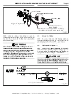
Set Air-Inlet Damper ‒ Figure 6
2.5.1
The inlet damper must be set to match the
cabinet dimensions and reclaimer size. The label on the
damper shows the settings in degrees. For the initial
setting, align the handle 30 degrees.
Figure 6
2.5.2
Loosen the lock nuts and position the damper
handle as noted. When correctly positioned, tighten the
lock nuts to maintain the setting. Refer to Section 5.7 for
adjustment procedure.
2.6
Final Assembly
2.6.1
Position the foot pedal on the foot shelf or on the
floor at the front of the cabinet. The foot shelf is easily
removed by removing the two release pins.
2.6.2
A package of five cover lenses is supplied with
the cabinet. To install a cover lens, remove the adhesive
backing and apply the lens to the clean, dry, inner
surface of the view window. Refer to Section 7.3. When
the cover lens becomes pitted or frosted, replace it.
3.0
FIELD INSTALLED ACCESSORIES
3.1
Aluminum Oxide (aggressive media) Kit
3.1.1
An optional aluminum oxide kit is available
factory installed or may be field installed later.
Factory-installed kits consist of black-rubber cabinet
curtains with grommets, curtain hardware, and a boron
carbide nozzle.
Field-installed (or replacement factory installed) kits
consist of black-rubber cabinet curtains (refer to Section
3.2 for curtain installation) a boron carbide nozzle, and
light-lined flex hose. If the existing flex hose is in good
condition, reserve the new hose for future replacement.
3.2
Cabinet Curtains Installation
3.2.1
Match curtains to corresponding wall and doors.
3.2.2 Front and rear walls:
Position the curtain on
the wall to be protected. Using the curtains as templates,
mark each mounting point through the grommet holes
along the upper edge of the curtain. NOTE: When laying
out the attachment points, the upper edge of the rear
curtain should be below the bottom edge of the air-duct
partition. Remove the curtains and drill a .187" (3/16")
diameter hole at each point marked. Install the curtains
using the fasteners provided (machine screw, 11/16
OD
flat washer, lock washer and nut) at each grommet. The
flat washer is used between the screw head and the
rubber curtain grommet on all curtains.
3.2.3
Doors:
Using protectors against the curtains
and outer doors, clamp the door curtains in place.
NOTE: When laying out the attachment points, the upper
edges of the door curtains should be even with the outer
edges of the door’s soundproofing panel. Insert a #10
self-drilling screw with an 11/16
OD flat washer through
the grommet holes. Use a screw gun with a 5/16" socket
to drill and thread the screws through the door’s inner
wall at each grommet.
3.3
Track and Low-Profile Table,
Maximum Weight Capacity 500 Lbs
3.3.1
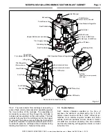
Components of track and table assembly are
shown in Figure 7. The assembly consists of:
1. Track assembly: mounts inside the cabinet.
2. Table assembly: rollers on sliding table fit inside the
track rails.
3. All necessary mounting fasteners.
Figure 7
NOTE: The track may be installed on either side of the
cabinet, so the table can slide out through either the
Damper Handle
Degrees Label
Align handle to degrees, as
noted in Paragraph 2.5.1.
Air-Inlet Damper
Table Assembly
Track Assembly
Mounting Holes
Mounting Holes
Rollers (4)
Track Rails


