Clemco MediPulse 2342se Скачать руководство пользователя страница 16


MEDIPULSE 2342se ERGONOMIC SUCTION BLAST CABINET 

Page 15


© 2019 

CLEMCO INDUSTRIES CORP.  

  www.clemcoindustries.com  

  Manual No. 24939, Rev. C, 03/19


5.8.1

  Refer to instructions packed with the manometer 

for preparing and operating the manometer. 
 

5.8.2

  Connect one end of the 3/16" ID tubing to one of 

the  tubing  connectors  (elbow)  at  the  top  of  the 
manometer by pushing it over the barbed adaptor. 
 

5.8.3

  Open  both  manometer  valves  (elbows),  per the 

instructions with the manometer. 
 

5.8.4

  Magnets on the manometer hold it in position on 

the  reclaimer  body  or  dust-collector  body.  The 
manometer must be vertical so the fluid is level on both 
sides.  
 

5.8.5

  Adjust  the  slide  rule  to  align  the  zero  with  the 

fluid level. Refer to Figure 21. 
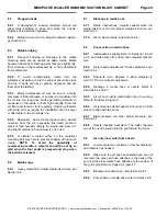
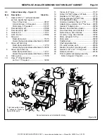
 
5.8.6


Needle  placement:

  Figure  20  shows  the 

manometer  setup  for  taking  both  periodic  and  frequent 
static-pressure readings. 


Figure 20 


5.8.6.1


Taking frequent readings using a permanent 

fitting:

  A  permanent  fitting  may  be  installed  in  the 

reclaimer wall, as shown in Figure 20, for taking frequent 
static-pressure readings. Permanent fittings must have a 
barb  to  accommodate  the  3/16"  ID  tubing  and  have  a 
means of sealing the fitting when the manometer is not 
in  use.  Use  silicone  sealer  or  other  sealant  to  seal 
 

around the fitting to prevent leaks. The fitting should be 
capable  of  being  capped  when  the  manometer  tube  is 
removed.  Sealing  the  fitting  will  prevent  leaks  that  alter 
the  reclaimer’s  separation  efficiency.  Air  drawn  into  the 
reclaimer will cause carry over of good media to the dust 
collector. 

 
5.8.6.2


To  take  occasional  readings: 

Leave  the 

needle protector on the needle and insert the needle into 
the  unused  end  of  the  tubing.  The  ends  of  the  tubing 
must  fit  tight  on  the  manometer  and  needle;  leaks  will 
give  inaccurate  readings.  Open  the  reclaimer  fill  door, 
remove  the  needle  protector,  and  place  the  needle  so 
the point is inside the door opening. Carefully close the 
door  on  the  needle.  The  side  of  the  needle  will  embed 
into the rubber door gasket, creating an airtight seal 
 

5.8.7

  Open cabinet doors and turn the exhauster ON. 

The negative (static) pressure will move fluid in the tube. 

NOTE:  Readings  must  be  taken  with  the  cabinet 
doors open and with the exhauster running. 


Figure 21 


The manometer must be vertical 

when taking pressure readings.

With the exhauster OFF, 

slide the rule to align the 

zero with the fluid level. 

To obtain the pressure reading: With the 
exhauster ON, add the number of 
inches the fluid travels up the column to 
the inches the fluid travels down the 
other column. The total is the static-
pressure reading. 

In the example shown, fluid traveled up 

the right column 1-3/4"

and down the left column 1-3/4".

 Static pressure is determined by adding 

the columns together. In the example, 

the static pressure is 3-1/2 ".


Refer to Paragraph 5.8.6.2. 
When taking occasional 
readings, position the 
needle so the point is inside 
the door opening. Carefully 
close the door on the 
needle. 

Refer to Paragraph 5.8.6.1. 
For taking frequent readings, 
remove plug and install a 
permanent fitting in the 
coupling, as shown. 

Reclaimers are for reference and 
may differ from those shown.


Reclaimer Fill Door 

Содержание MediPulse 2342se

Страница 1: ...ible that the products described in this material may be combined with other products by the user for purposes determined solely by the user No representations are intended or made as to the suitabili...

Страница 2: ...ates a hazardous situation that if not avoided could result in minor or moderate injury WARNING Warning indicates a hazardous situation that if not avoided could result in death or serious injury DANG...

Страница 3: ...PLACEMENT PARTS 9 0 Optional Accessories field installed 9 1 BNP Gun and Feed Assembly 9 2 Cabinet Assembly 9 3 LED Light Assembly 9 4 View Window 9 5 Metering Valve 9 6 Foot Pedal 9 7 Filter Regulato...

Страница 4: ...6 1 Unless otherwise specified at the time of purchase the cabinet is provided with a No 5 5 16 orifice ceramic nozzle and No 5 5 32 orifice air jet Optional more durable tungsten carbide and boron c...

Страница 5: ...formance from the reclaimer When using larger nozzles the maximum mesh size of media will be smaller than normally recommended Using media finer than those recommended may decrease visibility and at s...

Страница 6: ...g 1 2 HP 115 230V 1 PH 60 HZ motors wired for 115 volts FLA 20 7 208 3 4 240 3 5 1 10 2 A power cord with u ground plug is provided 2 0 INSTALLATION 2 1 General Installation Notes 2 1 1 Select a locat...

Страница 7: ...ssories 2 3 Ground the Cabinet 2 3 1 To prevent static electricity buildup attach an external grounded wire from an earth ground to the grounding lug on the left rear of the power module 2 4 Connect E...

Страница 8: ...lacement 3 2 Cabinet Curtains Installation 3 2 1 Match curtains to corresponding wall and doors 3 2 2 Front and rear walls Position the curtain on the wall to be protected Using the curtains as templa...

Страница 9: ...flow particle weight and size Reclaimer static pressure is set by adjusting the outlet damper refer to Section 5 4 to adjust static pressure Refer to Section 5 8 for manometer instructions 3 5 Reclai...

Страница 10: ...hown by removing the fitting s compression nut sliding it over the end of the tubing inserting the tubing into the fitting and tightening the nut onto the fitting 3 6 6 Refer to the differential press...

Страница 11: ...pen the fill door and stir media until it starts to flow Before the container becomes too heavy to easily manage replace the plug and empty the container Replace the plug when the reclaimer is empty o...

Страница 12: ...immediately WARNING Shut down the cabinet immediately if dust discharges from the dust collector or cabinet Check to make sure the dust collector filter cartridge is correctly seated and that it is no...

Страница 13: ...adjust pressure unlock the knob by pulling it out as shown in Figure 14 and turn it clockwise to increase pressure or counterclockwise to decrease pressure Pressure may drop slightly from closed line...

Страница 14: ...h finer media higher with coarser media Run the media through several blast cycles allowing the reclaimer to function with these settings Inspect media in the reclaimer and fines in the dust collector...

Страница 15: ...imum pulse pressure of 90 psi is attained and additional pulsing as described in Section 6 2 4 does not increase visibility or decrease differential pressure replace the cartridge per Section 7 9 5 7...

Страница 16: ...will cause carry over of good media to the dust collector 5 8 6 2 To take occasional readings Leave the needle protector on the needle and insert the needle into the unused end of the tubing The ends...

Страница 17: ...require more maintenance to the cabinet s media recovery system Friability of media Media that rapidly breaks down require more maintenance to the cabinet s media recovery system and dust collector 6...

Страница 18: ...e and after each use Figure 23 6 2 4 Additional cartridge pulsing The cartridge is pulsed each time the foot pedal is pressed or released Additional pulsing should be performed per the following instr...

Страница 19: ...n the inside of the cabinet To replace loosen the clamps with a screwdriver replace the gloves and tighten the clamps 7 1 3 Quick change type clampless installation Quick change gloves are held in pla...

Страница 20: ...media leakage around the view window or if gaskets are worn or otherwise damaged Figure 25 7 5 2 Remove the window and window frame per Section 7 6 7 5 3 Remove all the old gasket material and clean t...

Страница 21: ...e gasket to bond Repeat the process for each side compressing the ends to seal 7 7 3 Diffuser lens replacement 7 7 3 1 Remove the four nuts and washers that attach the light mount cover to the cabinet...

Страница 22: ...plate against the inner wall of the reclaimer 7 8 9 New self drilling sheet metal screws are provided with the wear plate while forcing the wear plate against the reclaimer wall install the screws thr...

Страница 23: ...e container and drape it over the top edge Reattach the container to the lid and latch the lock ring making sure the lid and clamp are secure Replacement liners are shown in Sections 9 11 7 9 12 Seaso...

Страница 24: ...1 9 Obstruction in flex hose between the cabinet hopper and reclaimer inlet Inspect hose for blockage 8 1 10 Paddle wheel worn Check wheel for wear 8 2 Abnormally high media consumption 8 2 1 Door on...

Страница 25: ...mer mounting bolt may help to prevent bridging of fine mesh media NOTE To avoid the possibility of compressing media a vibrator should be set up to start when the foot pedal is pressed and stop when t...

Страница 26: ...as indicated by the arrow on the exhauster housing If it does not rotate in the proper direction lockout and tagout electrical power and switch the motor leads as shown on the motor plate Refer to the...

Страница 27: ...k alignment If the switch does not engage the pulse when the cam follower rides onto the lobe the switch assembly is too far from the lobe Loosen the two screws on the bottom of the pedal slide the sw...

Страница 28: ...spect the foot pedal per Sections 8 17 2 8 17 3 and 8 17 4 Figure 32 8 18 A steady stream of air is heard within the dust collector when the foot pedal is not pressed 8 18 1 Cam follower does not ride...

Страница 29: ...tion 9 2 Retaining ring wide spray 12038 Nozzle nut wide spray 11916 or Nozzle guard wide spray 12295 Time delay door locks for both doors 24163 Tumble basket 2 gallon 12227 Automatic pulse kit 21773...

Страница 30: ...1914 Urethane covered 11574 2 O ring 08975 3 Gun body 11802 4 Lock nut air jet 11913 5 Rubber sleeve 12097 6 Air jet assembly with Item 5 No 4 12342 No 5 12343 No 6 12344 7 Fitting hose 3 8 NPT x 1 2...

Страница 31: ...66 11 Clamp for 4 hose 11577 12 Fitting 1 8 NPT elbow x 1 8 barb 11733 13 Regulator 1 8 NPT pilot 12715 14 Gauge pressure 1 8 NPT cbm 01908 15 Foot pedal with tubing 20194 16 Grommet media air hose 3...

Страница 32: ...ck No 1 Window glass 12 5 x 19 5 laminated 12212 2 Gasket 5 16 x 3 4 applied to cabinet per foot 6 feet required 00189 3 Gasket 5 32 x 3 4 applied to window frame per foot 6 feet required 00192 4 Cove...

Страница 33: ...w x 1 8 barb 11733 17 Tie nylon wire 12139 Figure 42 9 8 Filter Regulator Inlet Piping Assembly Figure 43 Item Description Stock No Filter regulator inlet piping assembly Includes all items shown 2152...

Страница 34: ...1 2 flare 11351 19 Hose end 1 2 barb x 1 2 female swivel 15002 20 Hose end 1 2 barb x 3 8 male NPT 06369 21 Blow off nozzle 13116 22 Air hose 1 2 specify ft required 12472 23 Gun assembly BNP No 5 st...

Страница 35: ...Stock No Repair kit diaphragm pulse valve 21600 1 Valve 1 diaphragm pulse 19578 2 Valve 3 way 12202 3 Fitting 1 8 NPT straight x 1 8 barb 11732 4 Nipple 1 8 NPT hex 01962 5 Actuator air pilot 19123 6...

Отзывы: