background image

8

P1798E   04/06

15STH.C

2. Product Description

The pulse nutsetter features
-

torque shut-off,

-

lever-start with soft-start valve,

-

has a lockable torque adjustment accessible from the outside

-

reversible, RH and LH operation,

-

generates less than 65 dB(A) when idling and at clockwise
rotation

-

generates less than 2,5 m/s² vibration when pulsing

-

Optional shut-off signal for connection to electronic verifier


For safety reasons, the tool must always be disconnected
from the air supply during connection and adjustment
work

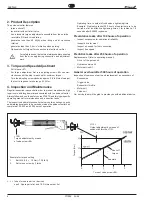
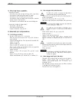
3. Torque and Speed Adjustment

-

Pull sleeve <97>.

-

For torque adjustment first turn adjusting screw< 85> counter-
clockwise until the stop is reached for minimum torque.

-

Turn the adjusting screw clockwise approx. 0-5 full turns to adjust
the tool to required torque range 5-15 Nm.

4. Inspection and Maintenance

Regular inspection is essential in order to prevent breakdowns, high
repair costs and long downtimes associated with the pulse nutsetter.

Always follow and use the safety notes P1687S and this type-specific
operating manual for maintenance and inspection tasks

The inspection and maintenance list below contains timings, checks
and maintenance tasks to be carried out when the pulse nutsetter has
completed 100, 250 and 500 hours of operation

<..> = Index for spare parts or devices

see 9. Spare parts list and 10. Fixtures order list

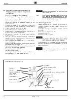
<100>
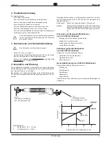
Torque adjustment by means
of valve screw <85>

Example for torque setting
1.

Bolt M6  8.8  =  10 Nm (~7,38 lb.ft)

2.

Set torque screw by 2 turns

Turns of valve screw <85>

Shut-off
torque

Torque (Nm)

Operating time = number of rundowns x tightening time

Example: Predicative tasks (250 hours of operation) are to be
carried out at an effective tightening time of, for instance, 1.8
seconds after 500000 rundowns

Preventative tasks after 100 hours of operation

-

Inspect suspension for operational reliability

-

Inspect drive for wear

-

Inspect air supply for firm connection

-

Inspect free speed

Predictive tasks after 250 hours of operation

Replacement of (refer to operating manual)

-

Oil out of the pulse unit

-

Hydraulic service kit

-

Motor service kit

General overhaul after 500 hours of operation

Inspection of component parts and replacement as necessary of

-

Suspension

-

Trigger valve

-

Exhaust air throttle

-

Motor unit

-

Pulse unit

Our service team will be glad to provide you with additional advice

<112>
Output adjustment by means of
exhaust air throttle <113>

Example

Содержание 15STH C Series

Страница 1: ...apacity Abtrieb Final drive 15 11 06 ft lb 15 Nm Q Schnellwechselfutter Quick Change 7 16 Design Speed S gerader Griff Straight handle 40 4000 1 min Abschaltung Torque control Ausf hrung Style T Torqu...

Страница 2: ...e pays de l utilisateur doivent tre obligatoirement respect es par toute personne charg e de l installation le fonctionnement et la maintenance de l outil S curit Lire d abord attentivement les consig...

Страница 3: ...enta sin haber le do y comprendido estas instrucciones y el manual espec fico de este modelo S mbolos Atenci n Este s mbolo indica un situaci n potencial de peligro Pueden producirse lesiones f sicas...

Страница 4: ...da medidos seg n ISO5393 1 4 37 5 Leerlaufdrehzahleinstellung Free speed adjustment Reglage de la vitesse vide Regolazione della velocit a vuoto Ajuste de la velocidad en vac o 6 2 bar 620 kPa 90 PSIG...

Страница 5: ...onsarbeiten immer Sicherheitshinweise P1687S und die typspezifische Betriebsanleitung beachten und ver wenden Nachfolgende Inspektions und Wartungsliste enth lt Zeit Kontroll und Wartungshinweise f r...

Страница 6: ...herungsringe Scheibe H lse Kugeln und Druckfeder des Schnellwechselfutters entfernen Impuls Einheit 102 aus dem Geh use 94 ausbauen Hydr Zylinder 89 mit Schl sselfl chen in glatte Schraubstock backen...

Страница 7: ...ontagehinweise Bild 6 Nicht verspannen da es sonst bei Hydr Zylinder 89 und Innenteilen zu Funktionsschwierigkeiten kommen kann Anmerkung Kleinere Blasen die bei hohem Unterdruck in der Benetzungsschi...

Страница 8: ...and maintenance list below contains timings checks and maintenance tasks to be carried out when the pulse nutsetter has completed 100 250 and 500 hours of operation Index for spare parts or devices s...

Страница 9: ...he oil filler unit A is available Pulse unit has to be at room temperature Remove quick change chuck retaining rings washer sleeve and compression spring Dismounting pulse unit 102 from the housing 94...

Страница 10: ...C Caution Caution Excessive vise clamping force may cause operating problems of the hydraulic cylinder 89 and the inside parts Remarks Small bubbles appearing at high vacuum pressure in the wetting l...

Страница 11: ...e et 10 Liste de commande des dispositifes La liste ci contre de contr le et de maintenance indique les consignes de maintenance de contr le et de temps pour 100 250 et 500 heures de service de la vis...

Страница 12: ...unit d impulsions la temp rature ambiante D monter les bagues de s curit rondelle douille et ressort pression du mandrin changement rapide D monter l unit d impulsions 102 du carter 94 Fixer les surfa...

Страница 13: ...s et la fermer avec la vis de fermeture 90 Tirer la goupille d arr t 71 et remplir la chambre d arr t qui se trouve en arri re avec l injecteur en vitant la formation de bulles Remonter la goupille d...

Страница 14: ...re ad impulsi Durante i lavori di controllo e manutenzione occorre utilizzare e osservare sempre le istruzioni per l uso specifiche e le indicazioni di sicurezza P1687S L elenco dei controlli e della...

Страница 15: ...dispositivo di riempimento dell olio depressometro A Togliere dal mandrino gli anelli di tenuta la rondella la guida e la molla di compressione Smontare l unit idraulica 102 dal corpo 94 Agganciare l...

Страница 16: ...dura di riempimento da 4 a 6 Fino a che non ci siano piu bolle d aria Scollegare l unit idraulica dal dispositivo di riempimento dell olio e avvitare la vite di regolazione 90 Togliere la spina di shu...

Страница 17: ...ico N de referencia en la lista de recambios o dispositivos Lasiguientelistadeinspecci nymantenimientocontieneinstrucciones sobre tiempo control y mantenimiento para las 100 250 y las 500 horas de ser...

Страница 18: ...illos de retenci n del mandril de cambio r pido la arandela manguito y muelle de compresi n Desmontar la unidad de impulso 102 de su alojamiento 94 Sujetar el cilindro hidr ulico 89 en un tornillo de...

Страница 19: ...dimiento de llenado 4 a 6 hasta que no se formen burbujas Desconectar la unidad de impulso del llenador de aceite y apretar el tornillo de bloqueo 90 Tirar del pasador de cierre 71 y llenar la c mara...

Страница 20: ...avec le convertisseur de couple hydraulique Montaggio della ghiera filettata sull unita idraulica Apriete del anillo de rodadura con la unidad de impulso 1 Voranzugs Md 50 5 Nm pretightening torque 37...

Страница 21: ...ade since last issuance Modifications aupr s des ditions derni re 11 04 Modificazioni rispetto l ultima edizione Cambios despu s de la ltima edici n Teil des Motor Service Kits 540037 Included in moto...

Страница 22: ...t a t n u j 5 1 X 5 2 1 2 2 4 1 6 5 1 9 1 e s h c u B g u l p e l l i u o d a l o c c o b o l l i u q s a c 3 2 2 5 8 2 0 9 1 g n i R O g n i r o e u q i r o t t n i o j O d a o l l e n a a c i r t a...

Страница 23: ...u r D g n i r p s n o i s s e r p m o c c i n o c n o i s s e r p t r o s s e r a c i l e d a a l l o m n i s e r p m o c e d e l l e u m X 3 3 2 X 5 5 1 X 6 1 8 1 5 6 7 2 1 8 2 9 1 l p k n e b l o K...

Страница 24: ...o c n o i s s e r p t r o s s e r e n o i s s e r p m o c i d a l l o m n i s e r p m o c e d e l l e u m 6 1 X 5 4 1 X 8 0 9 9 6 2 3 1 1 9 1 g n i R g n i r u a e n n a o l l e n a o l l i n a 0 0 1...

Страница 25: ...V 5 4 7 6 0 V g n i r n e l a k S g n i r e u g a b o l l e n a o d a u d a r g o l l i n a 2 C V 4 4 7 6 0 V u n k c e t S t e k c o s e l l i u o d l c a l o s s u b s e n o t e t e d e v a l l 3 C...

Страница 26: ...ve con tet n articulada Anschlu m glichkeit f r ein optionales Abschaltsignal in Verbindung mit einer Auswerteelektronik Optional shut off signal for connection to electronic verifier Option signal de...

Страница 27: ......

Страница 28: ...2 802 1718 Fax 425 497 0496 Fax 717 757 5063 Tel 905 501 4785 Fax 905 501 4786 Germany England France China Cooper Power Tools Cooper Power Tools Cooper Power Tools SAS Cooper China Co Ltd GmbH Co OHG...

Отзывы: