background image

CLEARSPAN

 POLY BUILDINGS

16

Revision date: 12.08.15

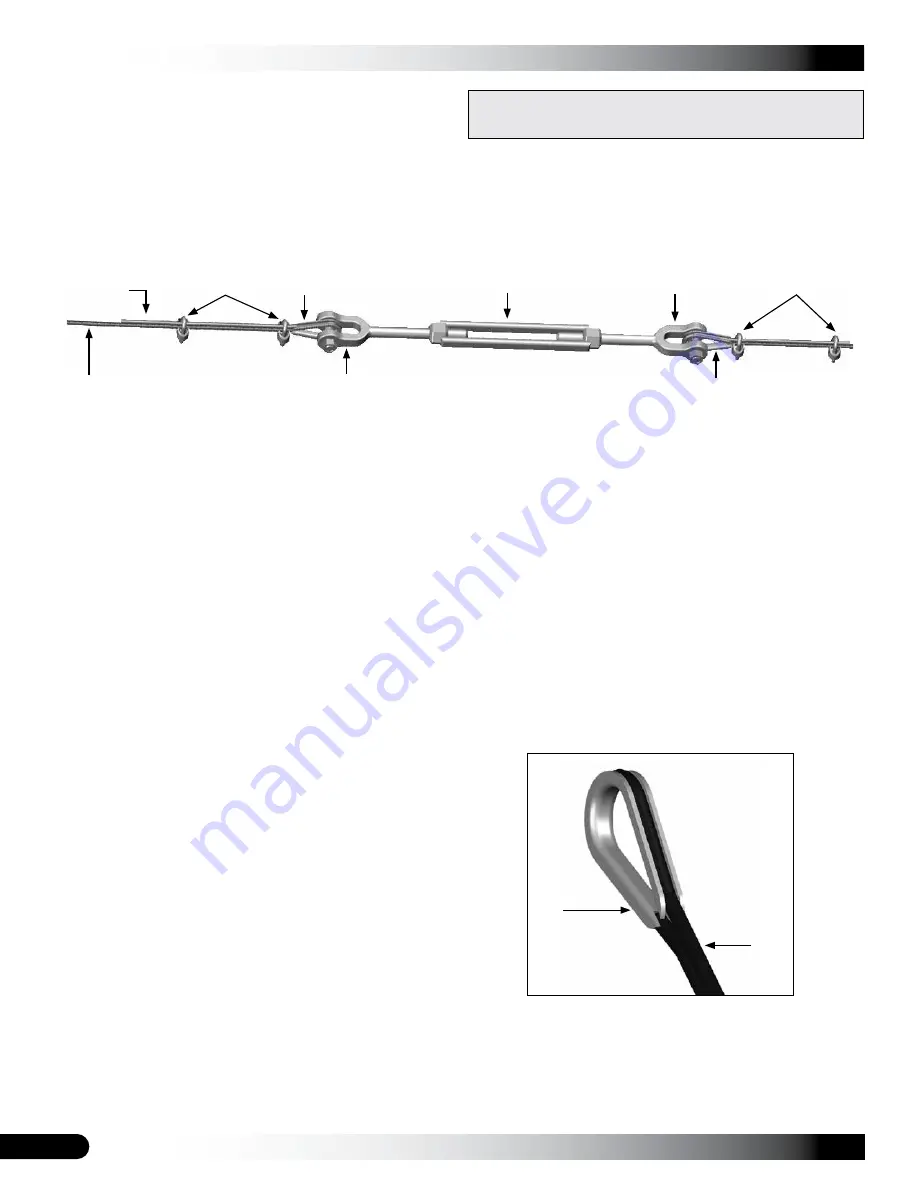
CABLE ASSEMBLY

Cable assemblies provide diagonal bracing.  

Each cable assembly includes the following items:
•  Cable (2 cables cut to length)
•  Turnbuckle (1)
•  Cable thimbles (4)
•  Cable clamps (4) 

NOTE: 

For each cable assembly, four (4) additional cable clamps are used to attach cable assembly to frame. In 

addition, Cable C assemblies require an additional cable thimble at each lower end to complete the connection to 

band clamp attached to end rafter leg. See Side Profile Diagrams. Consult Cable Diagram on following page and Side 

Profile diagram in Quick Start section for clarification and cable locations.

Cable Assembly Procedure

1.  Using the Side Profile Diagram in Quick Start section as a guide, measure distance needed on frame and cut 

cable to the proper length for each assembly. Remember to account for the turnbuckle and the cable length 

needed to attach thimbles at each end. (Extra cable has been sent for cabling.) Make a single assembly 

before


making them all. This allows a check to be sure the correct length has been cut. Make the necessary length 

adjustments as needed before making additional assemblies. To prevent running out of cable, 

always measure 

before cutting. 


ATTENTION:

 One (1) turnbuckle and two (2) cables are used for each cable assembly type. For best results and 

to reduce cable waste, use the diagram on the next page and measure the distance required for a specific cable 

type. Additional cable length is needed to anchor cable to frame and to attach cable sections to turnbuckle.  


Measure and cut the follow assemblies as needed:

2.  Place one cable thimble approximately twelve inches (12") 

from end of a cable section and wrap cable around thimble 

as shown in the figure to the right.

3.  Grasp both sections of the cable near the thimble and 

position one cable clamp one inch away from thimble as 

shown above. 


NOTE:

 Position clamp on cable with its U-bolt portion over 

the short/"dead" cable section.

4.  With the saddle portion of the cable clamp in position on 

the "live" cable section, thread nuts onto U-bolt section of 

clamp and tighten slightly to maintain clamp position.

Thimble

Cable

•  Cable Assembly A: 16 cable lengths; 8 turnbuckles
•  Cable Assembly B: 16 cable lengths; 8 turnbuckles
•  Cable Assembly C: 16 cable lengths; 8 turnbuckles

ATTENTION: 

Consult the diagram on the next page to 

identify cable assemblies and cable locations.

Cable Clamps

Thimble

"Live" Cable 

Section

Turnbuckle

Turnbuckle Jaw

Thimble

Turnbuckle Jaw

Cable Clamps

Typical Turnbuckle Assembly

"Dead" Cable 

Section

Содержание 30' Wide Pony Wall Building

Страница 1: ...rved Reproduction is prohibited without permission STK DIMENSIONS PB00812R4W 30 W x 19 H x 48 L PB00813R4W 30 W x 19 H x 60 L PB00814R4W 30 W x 19 H x 72 L ClearSpan 30 Wide Pony Wall Building Photo may show a model of a different length and design Height shown includes 4 pony wall ...

Страница 2: ...ion Improper anchoring may cause shelter instability and structure failure Failing to anchor shelter properly will void the manufacturer s warranty and may cause serious injury and damage LOCATION Choosing the proper location is an important step before assembly The following suggestions and precautions help determine whether the selected location is the best location Never erect structure under p...

Страница 3: ...cover and end panels if equipped Purlins and some strut assemblies also consist of connected pipes to form a conduit Each pipe joint of a conduit assembly is secured with a self tapping Tek screw Coupler or Fitting A part of the frame assembly where legs purlins and rafter pipes are inserted and secured In most instances 3 way and 4 way couplers are used In some larger applications couplers are us...

Страница 4: ...open the plastic bags containing fasteners QUICK START GUIDE For a quick overview of this shelter and its components consult Quick Start Guide near back of these instructions Pages of Quick Start Guide show exploded views of all critical connections Use the diagrams to assemble frame Consult remainder of these instructions for additional important assembly details SHELTER CARE AND MAINTENANCE Prop...

Страница 5: ... additional details and diagrams Some parts are not shown FA4482B Tek Screw QH1061 1 Ratchet 100441 Nut Setter Swaged Plain Swaged and Plain Rafter Sections QH1065 2 Ratchet AS1003 3 16 Cable Clamp AS1083 3 16 Cable Thimble 104189 Turnbuckle 102546 Cross Connector QH1070 Pipe Strap 103856 Band Clamp FAH325B FALB32B Carriage Bolt Nut 104302 Pipe Fitting w Plate ...

Страница 6: ...elter 1 Layout site and identify required parts for each procedure 2 Assemble all rafters 3 Assemble and anchor frame 4 Cut assemble and install all cables 5 Prepare and install main cover Instructions that follow describe assembling all rafters and then constructing the frame Depending on the number of individuals assisting with construction it may be best and more efficient to have someone assem...

Страница 7: ... an additional 6 12 to accommodate mounting plate dimensions which extend beyond end rafters Top of pony wall must be level Building frame will not assemble properly if wall top is uneven Pony wall thickness Thickness of pony wall must provide a surface for entire mounting base of each rafter foot See diagram to the right REMEMBER Building cover is attached to outside of pony wall Position rafters...

Страница 8: ...ill hole Wedge anchor bolt will not work properly if hole is too deep Mounting plate shown differs from actual plate Installation is same 2 Insert anchor bolt into one drilled hole Firmly tap with a hammer to secure wedge anchor into concrete NOTE Depending on wedge anchor bolt verify the washer and nut are attached before driving anchor bolt Striking bolt may cause thread damage and prevent nut i...

Страница 9: ... posts or pony wall ATTENTION To ensure rafter alignment position all mounting plates so flanges face toward the same end of building Customer is responsible for providing fasteners to secure mounting feet BUILDING MOUNTED ON SUPPORT POSTS Support Posts 30 Width center of plate to center of plate 4 center of plate to center of plate TOP VIEW SIDE VIEW 48 center of plate to center of plate 48 Suppo...

Страница 10: ...ate 12 08 15 BUILDING MOUNTED ON PONY WALL Pony Wall 4 center of plate to center of plate 30 Width center of plate to center of plate TOP VIEW 48 center of plate to center of plate 48 Pony Wall Pony Wall SIDE VIEW MOUNTING PLATE ONLY Flange ...

Страница 11: ...ection near back of this guide QH1070 straps should remain loose do not fully tighten at this time Evenly space brackets the same for each end rafter 4 Slide one 1 103856 band clamp onto the end of each rafter leg Tape clamp to rafter pipe if needed 5 Measure 10 from rafter end and mark a line on the inside surface of rafter Position bottom of QH1070 bracket on line and secure it to rafter using t...

Страница 12: ...mounting plates earlier procedure and attach one to each rafter end using an FAG363B 3 8 x 3 bolt and FALB04B 3 8 nut Install bolt so nut is toward inside of rafter 4 Stack all interior rafters in the same accessible location 5 Continue with frame assembly The 102546 cross connectors are installed during frame assembly ATTENTION After assembling interior rafters set them aside in an accessible are...

Страница 13: ... pony wall End rafter includes the QH1070 pipe straps attached earlier Tighten mounting bolts 2 Use rope cable or some other form of temporary bracing to hold rafter in position Plumb the end rafter NOTE Plumbing end rafter at this stage assists in setting remaining rafters 3 With first end rafter secured set first interior rafter in place and attach it to the mounting feet Tighten bolts ATTENTION...

Страница 14: ...xtend beyond edge of end rafter NOTE Align cross connector with pipe strap attached to end rafter End Rafter A Interior Rafter Purlin B Attach top center purlin first A B Tek Screw Step 8 Step 9 9 Return to each purlin and cross connector and secure cross connector to rafter and the purlin to cross connector See example in diagram above Position Tek screws so they will not contact cover once it is...

Страница 15: ...sh pipe between last interior rafter and final end rafter to complete the assembly Consult the spec sheet and Side Profile diagrams Quick Start for XX pipe identification NOTE Cables shown in the diagram above are installed in the next procedure Ratchets are shown attached to side of pony wall These are installed during cover installation steps 16 With frame assembled continue with cable assembly ...

Страница 16: ...t running out of cable always measure before cutting ATTENTION One 1 turnbuckle and two 2 cables are used for each cable assembly type For best results and to reduce cable waste use the diagram on the next page and measure the distance required for a specific cable type Additional cable length is needed to anchor cable to frame and to attach cable sections to turnbuckle Measure and cut the follow ...

Страница 17: ...d See the insert in the diagram below for Steps 11 and 12 12 Insert 5 16 x 5 carriage bolt FAH325B down through 5 16 hole add a 5 16 nut and tighten 13 Repeat Steps 11 and 12 for remaining rafter purlin position at the other end of frame 14 Attach cables to assembled frame See diagrams below and in Quick Start section of these instructions for details and cable locations Cable assembly length and ...

Страница 18: ...d cable locations View is from inside the shelter Apply duct tape over cables on end rafters to protect the main cover Carriage bolt runs through rafter and top center purlin on 6th rafter depending on spacing at each end Attach band clamp 103856 above lowest pipe strap QH1070 on end rafters only Once cable is attached and clamp is tightened secure clamp to the rafter using a Tek screw View is fro...

Страница 19: ...hets QH1065 Customer supplied fasteners for pony wall or support post materials Due to the different materials used to construct pony walls customer is responsible for supplying the required fasteners Consult the advice of a qualified professional contractor if needed Complete the following steps to secure ratchets to pony wall or support posts 1 Locate four 4 ratchets QH1061 and attach these to o...

Страница 20: ...of frame is complete continue with cover installation 24 Photo shows straps and cover already installed these items are installed later in the instructions Additional materials required to secure ratchets to concrete are not included and must be purchased by customer Materials and frame shown in the following diagrams may differ from actual items Consult the Attaching Rafter Feet to Concrete secti...

Страница 21: ...to arrive at the frame length Conduits are used to tighten and secure the main cover Consult the Side Profile diagram in Quick Start section for pipe identification 2 After assembling cover conduits locate main cover and unfold it on a clean smooth surface near frame Unfold cover with inside surface facing up and straps positioned at front and back of frame 3 Align cover ends with front and back o...

Страница 22: ...he cover stretch pockets if equipped are to the inside This will be the underside of cover when it is pulled into position 3 Once cover is pulled into position center it on frame end to end and side to side WARNING To prevent damage and injury do not leave cover unattended if it has not been properly secured 4 Locate straps at front and rear hems Feed through center slot in each end ratchet Operat...

Страница 23: ...l and cut an opening in conduit pocket as shown Photos show using a utility knife Cover design differs from actual shelter Procedure is the same NOTE When cutting pocket for strap do not cut through main cover Cut only the pocket material Cutting access to cover conduit as shown allows water to flow over pocket opening and not into pocket 2 Select one tie down strap CC5391 and insert one end throu...

Страница 24: ...duit NOTE The following procedure applies to shelters longer than 48 If building is 48 long or shorter skip the next section and continue by tightening side ratchets as described on Page 27 4 Repeat previous steps to install and slightly tighten remaining straps Photos below show examples of pony wall shelters and how to attach ratchets to secure main cover INSTALL MAIN COVER SIDE STRAPS continued...

Страница 25: ...er View shows cover as seen when standing inside the building looking up at end rafter Main Cover PVC Conduit Strap End Rafter Notched Stretch Hem Pocket Install PVC conduits near main cover ends to provide an additional tie down position Complete these steps to install conduit and strapping for main cover stretch pockets 1 Take first section of PVC conduit and feed into stretch pocket from bottom...

Страница 26: ...t and end rafter as strap is installed 10 Continue weaving strap around end rafter and PVC conduit working up and over rafter and down to other end of PVC conduit NOTE Keep strapping snug during this step but do not over tighten Also maintain a even distance between the top of the end rafter and the PVC conduit 11 After weaving strapping cut strap and tie it to frame to temporarily secure it 12 Ta...

Страница 27: ...N SIDE RATCHETS Verify that cover is in the desired position and centered on the frame Loosen and reposition if needed Continue with these steps to tighten side ratchets 1 Move to side ratchets attached to the outside of pony wall or support posts Begin with the pair of ratchets closest to center of pony wall and opposite each other 2 With someone on each side of the shelter tighten the first pair...

Страница 28: ...START GUIDE 30 Wide Pony Wall Building Frame shown may differ in length from actual frame See Side Profile diagram for specific building length to determine cable patterns and locations 30 0 Width 15 5 1 4 Height Grid Represents 12 Squares F FR RO ON NT T 4 0 ...

Страница 29: ...ine 9 QH1070 pipe straps for each end rafter Assemble end rafters identically to keep purlins running parallel to each other throughout frame length Consult frame assembly steps for additional details End QH1070 Interior 102546 End QH1070 Interior 102546 End QH1070 Interior 102546 End QH1070 Interior 102546 End QH1070 Interior 102546 End QH1070 Interior 102546 End QH1070 Interior 102546 End QH1070...

Страница 30: ...NTER 166S099 5 166P096 1 1 66 COVER CONDUIT PURLIN PIPE 4 0 RAFTER SPACING ON CENTER The letter R identifies ratchet position on pony wall 5 16 x 5 Carriage Bolt Location Band Clamp Band Clamp Band Clamp Band Clamp ATTENTION Wrap all cable and rafter connections with duct tape or similar material to protect cover once it is installed ...

Страница 31: ...CENTER 4 0 RAFTER SPACING ON CENTER 166S099 7 166P048 1 1 66 COVER CONDUIT PURLIN PIPE The letter R identifies ratchet position on pony wall 5 16 x 5 Carriage Bolt Location Band Clamp Band Clamp Band Clamp Band Clamp ATTENTION Wrap all cable and rafter connections with duct tape or similar material to protect cover once it is installed ...

Страница 32: ... pony wall 131S075 11 131P0735 1 72 0 OVERALL LENGTH ON CENTER 4 0 RAFTER SPACING ON CENTER 166S099 8 166P096 1 1 66 COVER CONDUIT PURLIN PIPE Band Clamp Band Clamp Band Clamp Band Clamp 5 16 x 5 Carriage Bolt Location ATTENTION Wrap all cable and rafter connections with duct tape or similar material to protect cover once it is installed ...

Страница 33: ...nd Rafter Purlin Connection View 1 Mid Rafter Purlin Connection View 2 Purlin Rafter 102546 End Rafter Purlin Connection View 1 Mid Rafter Purlin Connection View 2 End Rafter ATTENTION Wrap all cable and rafter connections with duct tape or similar material to protect cover once it is installed ...

Отзывы: