Page 31 of 41
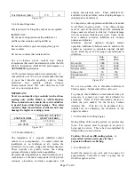
There should be approximately 0.03" air gap between
the top of the ring gear and the center of the magnetic
pick-up. The magnetic pickup on the ZF6H is bolted
onto the flywheel housing and is non-adjustable.
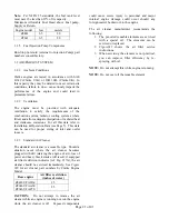
With the engine operating at rated speed, the output
voltage on the mag pickup should be between 4
VAC(rms) – 14 VAC(rms).
3.5.5
Mechanical Engine Control and Alarm Board
(MECAB) Speed Switch Troubleshooting
This engine is equipped with a speed switch capable
of sensing engine sensor malfunctions and/or
electrical over-current(s) on engine alarm circuits
and alerting the user via flashing status lamps. This
flashing status indication is done so with the red
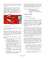
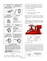
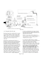
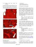
“OVERSPEED SHUTDOWN” lamp on the outside of
the Clarke instrument panel (Figure #29) and a red
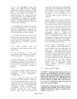
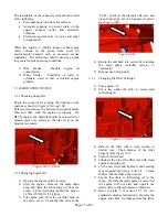
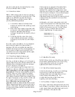
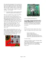
LED located on the middle of the speed switch inside
of the Clarke instrument panel (Figure #30). In
addition to these flashing status lamps, a “Low
Engine Coolant Temperature Alarm” is sent via
engine / fire pump controller inter-connect circuit
#312 as a means to alert the user outside of the
engine room.
NOTE: When first applying battery power to the
engine, or after activating the overspeed reset switch,
the OVERSPEED SHUTDOWN lamp and red LED
on the speed switch will flash several times. This is
an “INITIALIZATION PATTERN” and is normal.
This will be referred to in the following
troubleshooting section.
Figure #29
Figure #30 – MECAB speed switch
List of Troubleshooting Malfunctions
Two (2) blinks – Electrical Current Exceeds 10
Amps on Alarm Circuits:
Status lamps will flash
two times continuously on the Clarke instrument
panel and a “Low Engine Coolant Temperature”
alarm will be sent to the fire pump controller via
circuit #312.
Cause:
Electrical current exceeds 10 amps on one or more
engine / fire pump controller inter-connect circuits
Engine run alarm (#2)
Engine overspeed alarm (#3)
Engine low oil pressure alarm (#4)
Engine high coolant temperature alarm (#5)
Engine low coolant temperature alarm (#312)
Corrective actions:
Check each of the above circuits to determine which
contains the current overload.
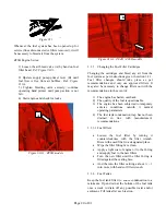
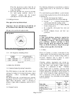
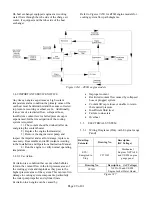
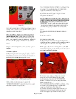
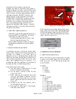
Once circuit(s) overload are corrected: On the Clarke
instrument panel, operate the “OVERSPEED
RESET” switch for two (2) seconds and release
(
Figure #31
).

