Page 29 of 41
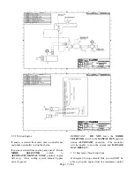
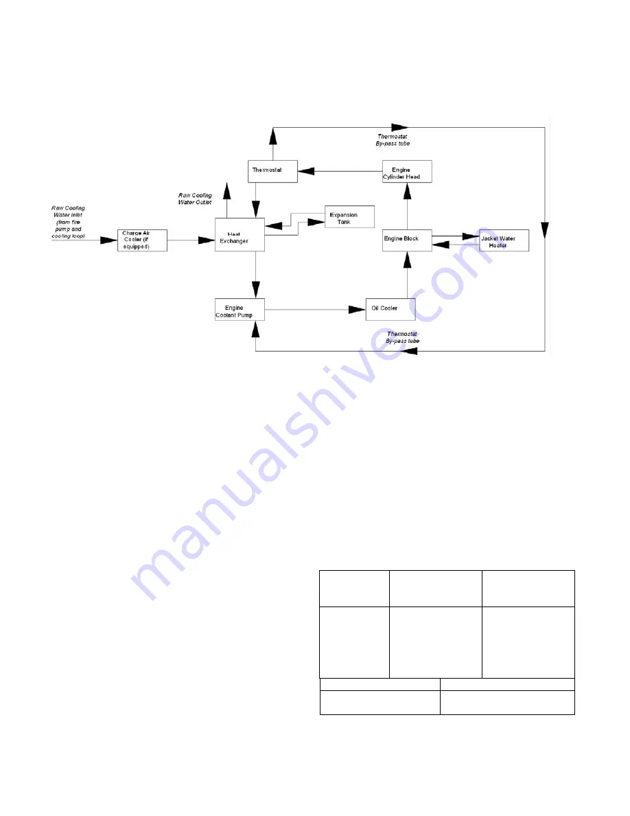
On heat exchanger equipped engines raw cooling
water flows through the tube side of the charge air
cooler, if equipped, and the tube side of the heat
exchanger.
Refer to
Figures #35E
for ZF6H engine models for
cooling system flow path diagrams.
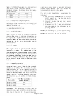
Figure #26A – ZF6H engine models
3.4.9 IMPORTANT SERVICE NOTICE
Any time an engine experiences a high coolant
temperature alarm condition the primary cause of the
overheat must be determined and the cause corrected
to prevent a recurring overheat event.. Additionally,
if an event of a restricted flow, collapsed hose,
insufficient coolant level or failed pressure cap is
experienced, further investigation of the cooling
system is required.
1) The coolant shoud be drained (after de-
energizing the coolant heater
2) Replace the engine thermostat(s)
3) Remove the engine water pump and
inspect the impeller and seal for damage, replace as
necessary. Reassemble and refill coolant according
to the Installation and Operations Instruction Manual.
4) Run the engine to verify normal operating
temperature.
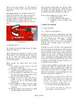
3.4.9.1 Cavitation
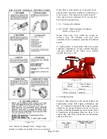
Cavitation is a condition that occurs when bubbles
form in the coolant flow in the low pressure areas of
the cooling system and implode as they pass to the
higher pressure areas of the system. This can result in
damage to cooling system components, particularly
the water pump impeller and cylinder liners.
Cavitation in an engine can be caused by:
Improper coolant
Restricted coolant flow caused by collapsed
hose or plugged system
Coolant fill cap is loose or unable to retain
the required pressure
Insufficient fluid level
Failure to de-aerate
Overheat
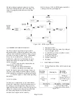
3.5
ELECTRICAL SYSTEM
3.5.1
Wiring Diagrams (Only with Engine Gauge
Panel)
Run/Stop
Solenoid
Drawing No.
Description
(DC Voltage)
ETS =
Energized to
Stop
C072145
Mechanical
Engines NFPA-20
and UL/FM engine
gauge panel
Drawing No.
Description (AC Voltage)
C07651
NFPA-20 and UL/FM
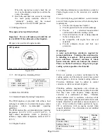
Engine Jacket Water Heater
Figure #27


