Page 30 of 41
3.5.2
Checking Drive Belt Tension and
Adjustment
All drive belts must be adequately tightened to secure
that both the engine water pump, fuel transfer pump,
and battery charging alternator (when fitted) are
operating efficiently. Refer to
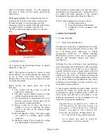
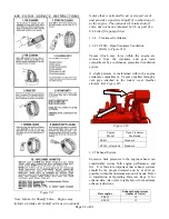
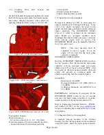
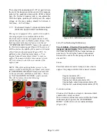
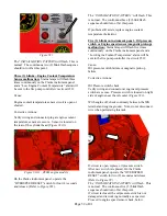
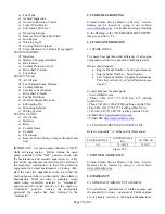
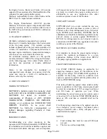
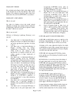
Figures #28,28A,28B
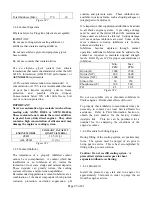
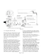
Figure #28 – ZF6H drive belts layout
Figure #28A – ZF6H fuel transfer pump tensioner,
rear belt
Figure #28B – ZF6H alternator tensioner, front belt
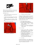
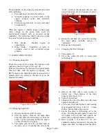
To adjust Belt Tension:
Check belt tension:
- Give at arrow must be 0.4” - 0.6” (10-15mm).
To increase tension of the water pump driving belts:
- Loosen alternator or belt tensioner mounting
bolts A and B.
- Adjust to proper belt tension.
- Tighten mounting bolts A and B.
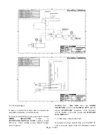
3.5.3 Speed Switch (when supplied)
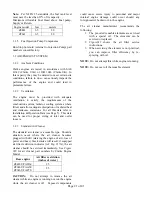
Overspeed is defined as 120% of rated speed for
engines rated from 1470 through 2600 rpm. In the
event of an engine overspeed, the speed switch
signals the main pump controller and also affects an
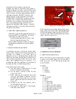
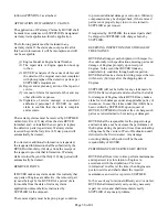
engine shutdown. The OVERSPEED RESET
(
Figure# 9
) switch is included on the instrument
panel. Should an overspeed condition occur,
investigate the cause and make necessary corrections
before placing engine back in service. The
OVERSPEED RESET must be manually lifted for
two (2) seconds to reset.
NOTE: This reset operation must be
completed to allow a restart. If not, the
engine will not start thru the main pump
controller or manually.
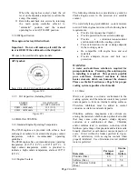
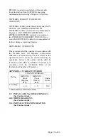
OVERSPEED VERIFICATION
Hold the OVERSPEED VERIFICATION switch in
the “up” position. This will provide the main pump
controller with an overspeed signal and engine
shutdown at 67% of the set overspeed RPM. Start
the engine via the main pump controller; the speed
switch will generate an overspeed signal and
shutdown protecting both the engine and pump.
EXAMPLE
Rated Speed: 1760 RPM
Overspeed Shutdown: 2112 RPM (120% of
1760 RPM)
Verification Shutdown: 1410 RPM (67% of
2112 RPM)
CAUTION-
after verification of overspeed, lift the
OVERSPEED RESET switch for two (2) seconds
and reset the main pump controller to re-instate
normal operation of the engine and speed switch.
Refer to Engineering Technical Bulletin – ETB003,
part number C133407, on the
www.clarkefire.com
website for adjusting the overspeed setting for range
rated engines.
3.5.4 Magnetic Pick-Up (when supplied)
A magnetic pick-up, mounted in the flywheel
housing, provides the input signal for the tachometer
overspeed switch, and/or the main pump controller.
B
B


