9
the sprocket at the base of the column enters the opening in the base cleanly, without touching
the sides, (as this could damage the sprocket).
Ensure also that the cable, which protrudes from the channel, welded to the columns’ bottom plate
(shown in fig. 4), is not trapped between the plate and base.
Secure to the Base Frame using the four screws, and large flat washers provided,in the corner bolt
holes ONLY, leaving them finger tight at this stage.
DO NOT use the centre holes
.
Carry out the same procedure for the other column.
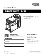
Place Chocks here
1234567890
1234567890
1234567890
1234567890
1234567890
1234567890
1234567890
Fig. 6
Fig. 7
Fig. 8
Fig. 9
Fig. 5
3. THE CHAIN
3.1 Before attaching the chain, you must first ensure the Arm
Carriages are at the same height, measured from the columns’
Base Plate. If an adjustment is required, remove the dust cover
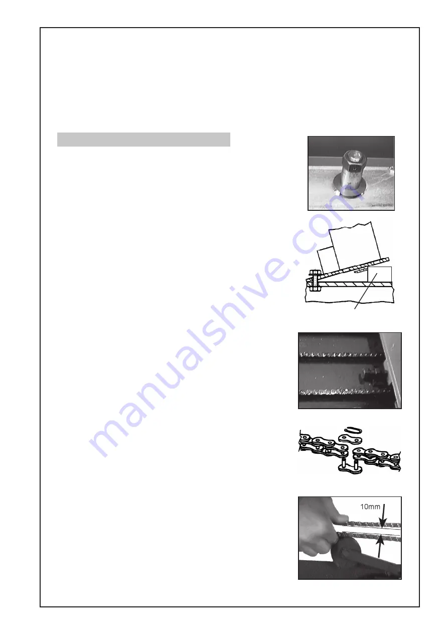
from the top of the Driven column and turn the hex. nut (on top
of the column, shown in fig. 5),until the carriage is perfectly in
line with that of the Drive Column. Replace the Dust Cover
3.2 Remove all but the two ‘outside’ column mounting screws and
slacken these off sufficiently so that the column may be tilted
outwards (see fig.6), in order to allow the chain to be slipped
around the sprocket.
Before tilting the column outwards however, slacken off the chain
adjuster screw, shown in fig. 7, fully, and make sure the column is
pushed in, towards the opposite column, as far as possible.
3.3 Very carefully tilt the column outwards and, as a safety
precaution, place chocks between the columns’ Base Plate
and the Base Frame as shown in fig. 6. (Should the column slip,
the chocks will prevent the column from injuring the hands of
the person manipulating the chain.
3.4 Slip the chain around the sprocket so that the end of the chain
reaches approximately half way across the Base Frame.
3.5 Once the chain is connected, remove the chocks, lowe the
column and screw down the column mounting screws again,
leaving them finger tight.
3.6 Proceed to connect the chain to the sprocket in the other column in
a similar manner,ensuring that the run of chain, from one sprocket
to he other, is as tight as you can get it,
without
turning the sprocket,
(as this will cause the carriages to become missaligned).
3.7 The two ends of the chain can now be brought together and
joined using the quick coupling provided (fig.8).
3.8 Once the chain is in place, it must be adjusted by screwing the
adjuster screws, (fig. 7), clockwise.
Screw in each adjuster, in turn, by a similar amount - say ½ turn
each side, until the gap at the centre, between the two runs of the
chain, is 10mm when using reasonable force of the thumb and
forefinger of one hand only. (see fig.9).
This microswitch is a safety feature, and operates when the
chain becomes too slack (less than 10mm gap at the centre of
the run), or breaks, shutting off the power to the motor.
3.9 Finally, connect the two electric cables, one from the base of
each Column, to the leads from the microswitch, using the two
waterproof in-line connectors packed in the parts bag.
Trim the cables back so that there is as little slack in the cable as
possible, to prevent any possibility of the connector, or the
cable, coming into contact with the chain.
Содержание Strong-Arm CPL30S
Страница 1: ...1 2 POST VEHICLE LIFT Model Nos CPL30S CPL30T OPERATING MAINTENANCE INSTRUCTIONS 0201...
Страница 2: ...2 Copyright Clarke International July 1999 All rights reserved...
Страница 21: ...21...
Страница 22: ...22...


