11
Release pressure on the safety nut and the spring will push the nut upwards, locking its threads with
those on the bar, thereby locking the bar in place.
To test its operation, press down on the safety nut and the threads should disengage, allowing the
arm to move freely. If it proves to be difficult to disengage the threads by pushing down on the nut,
it will be necessary to reposition the boss of the safety arm, on the pivot pin on the carriage.
If the safety bar is locked, i.e. the threads will not disengage when the safety nut is pressed down,
apply an upward pressure to the safety bar whilst pushing down on the safety nut, thereby
disengaging the threads, then get an assistant to swing the arm in order to withdraw the safety bar
from the safety nut and housing.
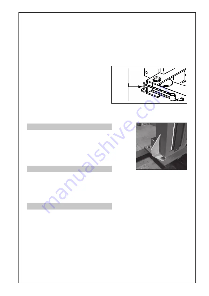
Flat washer placed
on the pin before the
Safety Bar is refitted
Fig. 14
Pull the safety bar from the pivot pin,place a flat
washer (provided) on to the pin and replace the
bar. Connect the bar to the safety nut as
previously described and retest to ensure the bar
releases correctly when the safety nut is pressed
down.
If necessary, repeat the operation, by placing
another washer on the pin, until the safety bar
locks and releases satisfactorily.
When completely satisfied, fit the circlip (16), to the pivot pin, and screw the self locking nut on to
the end of the safety bar,to its full extent. i.e. ensure the threaded safety bar is completely through
the nut and is gripped by the nuts’ nylon insert.
7. The Foot Guards
The four Foot Guards are safety devices and must be in place.
They are designed to prevent people from casually standing
on the base of the column, with a foot extended into the Free
Safety Area, thereby inviting the arm carriage or arm, to crush
the foot on its downward travel.
They are located with a single Column mounting bolt as
shown in fig. 14.
8. The Safety Guides
Safety Guides are provided which are bolted, one to each carriage, and can be clearly seen in fig.,
1, mounted immediately above the arms.
Each guide has rubber pads at each end of the guide bar to prevent serious damage to a vehicle
if it is not driven or positioned correctly between the columns. The safety guides also affords some
protection for the columns themselves.
These guides should now be bolted the carriage, in the manner shown in fig. 1.
9. Final Adjustments
The machine is now ready for final adjustment. This involves securing the columns firmly to the base
frame, and bolting the complete assembly to the floor ensuring the columns are perpendicular, and
perfectly in line with each other.
Firstly, screw down the column mounting screws, progressively, to a torque setting of 32lbft (43Nm).
Using a large spirit level, ensure the columns are perpendicular, in both directions, and in line with
each other. Any misalignment may be corrected with shims placed beneath the base frame at
strategic points. Remember, the floor should be properly prepared beforehand, and should be
perfectly level and flat at the area supporting the lift. This will simplify the job of aligning the columns.
All mounting points must be in solid contact with the floor, and any gaps between the base frame
and the floor, must be taken up with suitable shims (‘U’ shaped at the mounting bolts), of at least
80x80mm dimension.
When completely satisfied, tighten the bolts progressively to the torque setting recommended by
the foundation bolt manufacturers.
Содержание Strong-Arm CPL30S
Страница 1: ...1 2 POST VEHICLE LIFT Model Nos CPL30S CPL30T OPERATING MAINTENANCE INSTRUCTIONS 0201...
Страница 2: ...2 Copyright Clarke International July 1999 All rights reserved...
Страница 21: ...21...
Страница 22: ...22...


