background image

14

CJ-981E

English

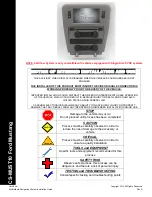
5. Temporarily remove the display unit.

Lift up the display unit while pressing down
on the unlock knob to temporarily remove the
display unit.

While pressing down

Lift up.

6. Attach the stand base to the determined

location on the attachment surface.

Remove the peel-off sheet from the base of
the stand base, and firmly attach the stand
base to the determined location (e.g. glove
compartment).

Notes:

• Before attaching the stand base, be sure to wipe

the attachment surface clean.

• After attaching the stand base, press down hard

so that the stand base is firmly attached to the
attachment surface.

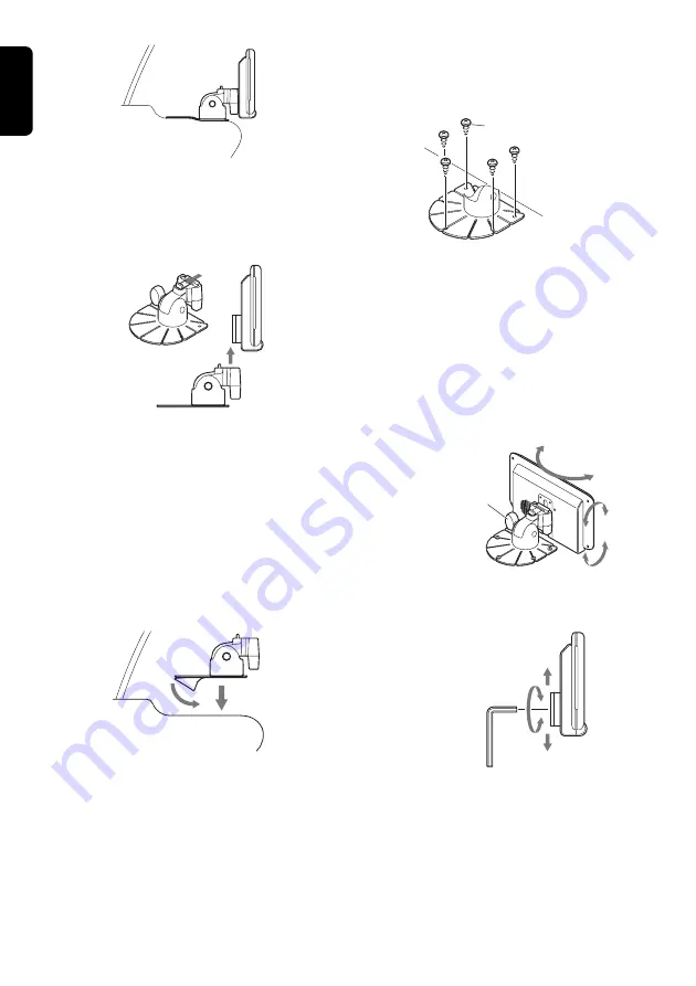
7. After attaching the stand base, fasten in

place with screws.

Fasten the stand base using the self-tapping
screws (provided).

Note:

• Sometimes strong adhesion between the stand

base and the attachment surface cannot be
obtained by the double-sided adhesive tape alone

depending on the material of the attachment
surface or heat. For extra safety, firmly fasten the
stand base in place using the self-tapping screws.
(In this case, note that screw holes will be drilled
into the attachment surface.)

Self-tapping screws
 (provided)

8. After about 24 hours, install the display unit

and adjust its angle for ease of viewing.

Front/back, left/right:

Loosen the angle adjustment screw to
adjust the angle.

Top/bottom:

Temporarily remove the display unit from
the monitor stand, and loosen the screw
with the Allen key (provided) and adjust the
position of the guide holder.

Loose the angle 
adjustment screw, 
and adjust the 
front/back and 

left/right angles.

After adjusting the angle, firmly tighten the
screws to fasten the display unit in place.

After adjustment, 
tighten and fasten.

Note:

• Vibration sometimes causes the monitor stand

screws to become loose. Periodically inspect and
re-tighten any loose screws.

Содержание CJ-981E

Страница 1: ...safety scale marks displayed onscreen assist the driver in determining distances to obstacles Backlight compensation function The camera s aperture iris can be adjusted to provide brighter viewing und...

Страница 2: ...e linked setting CAM3 AUTO CAMERA3 image linked setting CAM2 HAZARD CAMERA2 hazard linked setting CAM3 HAZARD CAMERA3 hazard linked setting During display of images from CAMERA2 or CAMERA3 the MARKER...

Страница 3: ...h hard objects Do not leave the LCD panel while it is wet since discoloration or stains may occur or moisture may invade the interior of the unit resulting in damage In the event water drops are splas...

Страница 4: ...benzene thinner or other volatile chemical cleaners to clean the screen This equipment has been tested and found to comply with the limits for a Class B digital device pursuant to Part 15 of the FCC R...

Страница 5: ...mode screen Setting Item BRIGHT luminance HUE color tone COLOR saturation DIMMER screen brightness Darker Redder Less Darker Lighter Greener More Lighter When in the VTR mode the screen will change to...

Страница 6: ...switch to CAM mode 2 Use the SELECT z button to select the CAMERA1 image 3 Press the MODE button to switch to the MARKER menu Each time the MODE button is pressed the mode cycles through the modes in...

Страница 7: ...s in the following order CAM MARKER MARKER ADJUST CAM 4 Press the z and w buttons as required to adjust the scale marker position up down The marker display position can be moved 10 steps above V 1 to...

Страница 8: ...reset and restarts from the newly reset time Setting the Camera Linked Image Switch CAM AUTO CAM HAZARD Automatic linked display This setting is used to select whether the camera image is automatical...

Страница 9: ...the CCD Camera s Image ZOOM Function This function operates only when a zoom equipped CCD camera is connected and when the CAM TYPE setting has been used to select a zoom equipped camera 1 Press the Z...

Страница 10: ...rn to the ordinary dimmed screen the indicator DIM will once again appear at the top of the screen 3 To dim the screen when the parking lamps are OFF hold the CAM1 DIM button depressed for about 1 sec...

Страница 11: ...d Display Unit Note Clean away all dust and dirt from the installation surface before installing 1 Lift up the guide holder while pressing down on the unlock knob to remove the guide holder Guide hold...

Страница 12: ...ttachment surface cannot be obtained by the double sided adhesive tape alone depending on the material of the attachment surface or heat For extra safety firmly fasten the stand base in place using th...

Страница 13: ...icator appears on the screen hold the CAM1 DIM button depressed for about 1 second to set dimmer to OFF This may occur when internal vehicle temperatures are below 0 C or above 60 C Adjust vehicle pas...

Страница 14: ...16 CJ 981E English...

Страница 15: ...safety scale marks displayed onscreen assist the driver in determining distances to obstacles Backlight compensation function The camera s aperture iris can be adjusted to provide brighter viewing und...

Отзывы: