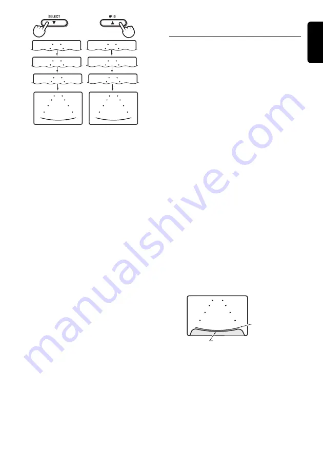
background image

CJ-981E

9

English

MARKER
SELECT

P7

MARKER
SELECT

P1

MARKER
SELECT

P3

MARKER
SELECT

P6

MARKER
SELECT

P2

MARKER
SELECT

P7

MARKER
SELECT

P1

MARKER
SELECT

P1

5. Press the [

MODE

] button to return to the

CAM

” mode screen.

Adjusting the Bumper
Position (MARKER ADJUST)

The display position of the scale markers set on
the screen can be adjusted to more closely
match the actual position of the vehicle’s
bumper.

Note:

• Different camera types are equipped with different

scale marker patterns. Be sure to set the “

CAM

TYPE

” first, and only then set the marker adjust.

1. Press the [

FUNC

] button and switch to the

CAM

” mode screen.

2. Press the [

SELECT

] (

z

) button and switch

to the CAMERA1 image.

3. Press the [

MODE

] button and switch to the

MARKER ADJUST

” setting menu.

Each time the [

MODE

] button is pressed the

menu alternates in the following order:

CAM

” 

 “

MARKER

” 

 … “

MARKER

ADJUST

” … 

 “

CAM

4. Press the [

z

] and [

w

] buttons as required

to adjust the scale marker position up/down.

• The marker display position can be moved

10 steps above (V+1 to +10) and 10 steps
below (V-1 to -10) the default position. The
amount of perpendicular movement is
indicated on the screen.

• When the markers are moved from their

default position, the more the onscreen
markers move, the more they vary from
representing their actual physical position.
In such cases, it is safest to adjust the
bumper position marker a bit above the
actual position of the bumper as shown in
the screen.

MARKER
ADJUST

P1

H+10
V   -5

Bumper position 
marker

Bumper image

5. Use the [

Å

] and [

Î

] buttons to adjust the

marker positions left/right.

• The marker display position can be moved

10 steps to the left (H+1 to +10) and 10
steps to the right (H-1 to -10) from the
default position. The amount of horizontal
movement is indicated on the screen.

6. Press the [

MODE

] button to return to the

CAM

” mode screen.

Содержание CJ-981E

Страница 1: ...safety scale marks displayed onscreen assist the driver in determining distances to obstacles Backlight compensation function The camera s aperture iris can be adjusted to provide brighter viewing und...

Страница 2: ...e linked setting CAM3 AUTO CAMERA3 image linked setting CAM2 HAZARD CAMERA2 hazard linked setting CAM3 HAZARD CAMERA3 hazard linked setting During display of images from CAMERA2 or CAMERA3 the MARKER...

Страница 3: ...h hard objects Do not leave the LCD panel while it is wet since discoloration or stains may occur or moisture may invade the interior of the unit resulting in damage In the event water drops are splas...

Страница 4: ...benzene thinner or other volatile chemical cleaners to clean the screen This equipment has been tested and found to comply with the limits for a Class B digital device pursuant to Part 15 of the FCC R...

Страница 5: ...mode screen Setting Item BRIGHT luminance HUE color tone COLOR saturation DIMMER screen brightness Darker Redder Less Darker Lighter Greener More Lighter When in the VTR mode the screen will change to...

Страница 6: ...switch to CAM mode 2 Use the SELECT z button to select the CAMERA1 image 3 Press the MODE button to switch to the MARKER menu Each time the MODE button is pressed the mode cycles through the modes in...

Страница 7: ...s in the following order CAM MARKER MARKER ADJUST CAM 4 Press the z and w buttons as required to adjust the scale marker position up down The marker display position can be moved 10 steps above V 1 to...

Страница 8: ...reset and restarts from the newly reset time Setting the Camera Linked Image Switch CAM AUTO CAM HAZARD Automatic linked display This setting is used to select whether the camera image is automatical...

Страница 9: ...the CCD Camera s Image ZOOM Function This function operates only when a zoom equipped CCD camera is connected and when the CAM TYPE setting has been used to select a zoom equipped camera 1 Press the Z...

Страница 10: ...rn to the ordinary dimmed screen the indicator DIM will once again appear at the top of the screen 3 To dim the screen when the parking lamps are OFF hold the CAM1 DIM button depressed for about 1 sec...

Страница 11: ...d Display Unit Note Clean away all dust and dirt from the installation surface before installing 1 Lift up the guide holder while pressing down on the unlock knob to remove the guide holder Guide hold...

Страница 12: ...ttachment surface cannot be obtained by the double sided adhesive tape alone depending on the material of the attachment surface or heat For extra safety firmly fasten the stand base in place using th...

Страница 13: ...icator appears on the screen hold the CAM1 DIM button depressed for about 1 second to set dimmer to OFF This may occur when internal vehicle temperatures are below 0 C or above 60 C Adjust vehicle pas...

Страница 14: ...16 CJ 981E English...

Страница 15: ...safety scale marks displayed onscreen assist the driver in determining distances to obstacles Backlight compensation function The camera s aperture iris can be adjusted to provide brighter viewing und...

Отзывы: