Page 16
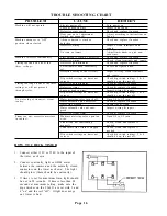
CAUSE
Electric power off.
Loose or broken wires.
Defective start switch.
Door cam out of adjustment
(switch not engaged).
Advance button is stuck or
defective.
Defective wiring.
No time on timers.
Start button is stuck or defective.
Defective wiring.
Defective potentiometer.
Potentiometer knob incorrectly
set.
Defective wiring or short circuit.
Dip switch settings on timer not
correct.
Defective potentiometer.
Defective timer.
Loose or broken wires.
Dip switch settings on timer not
correct.
Water metering valve turned off.
Water solenoid valve defective.
Water line clogged.
Water solenoid valve not ener-
gized.
Defective steam timer.
Moisture metering valve open too
wide.
Steam trap not functioning
properly.
Condensate line strainer clogged.
Dip switch settings on timer not
correct.
REMEDY
Turn power on.
Inspect and repair.
Check and replace if needed.
Adjust according to instructions on
Page 9.
Check and replace if needed.
Inspect, clean terminals and
repair.
Adjust timer knobs to give non-
zero time.
Check and replace if needed.
Check, clean terminals and repair.
Check and replace if needed.
Reset and tighten knob.
Inspect wiring, clean terminals
and repair.
Check dip switch settings, 3 & 4
should be on, the rest off.
Check & replace if needed.
Check & replace if needed.
Inspect wiring & repair.
Check dip switch settings, 3 & 4
should be on, the rest off.
Open 1/4 to 1/2 turn.
Check & replace if needed.
Locate line & clean.
Inspect wiring & repair.
Check & replace if needed.
Open 1/4 to 1/2 turn.
Check, clean, and replace if
needed.
Check, clean, and replace if
needed.
Check dip switch settings, 3 & 4
should be on, the rest off.
PROBLEM
Machine will not operate.
Machine advances to OFF
position when started.
Machine re-cycles continuously.
Timing too short on one of the
three settings.
Timing too long on one of the three
settings or will not proceed
through cycles.
No water fog at steam jet; steam
too dry.
Steam too wet; excessive moisture
in cabinet.
TROUBLE SHOOTING CHART
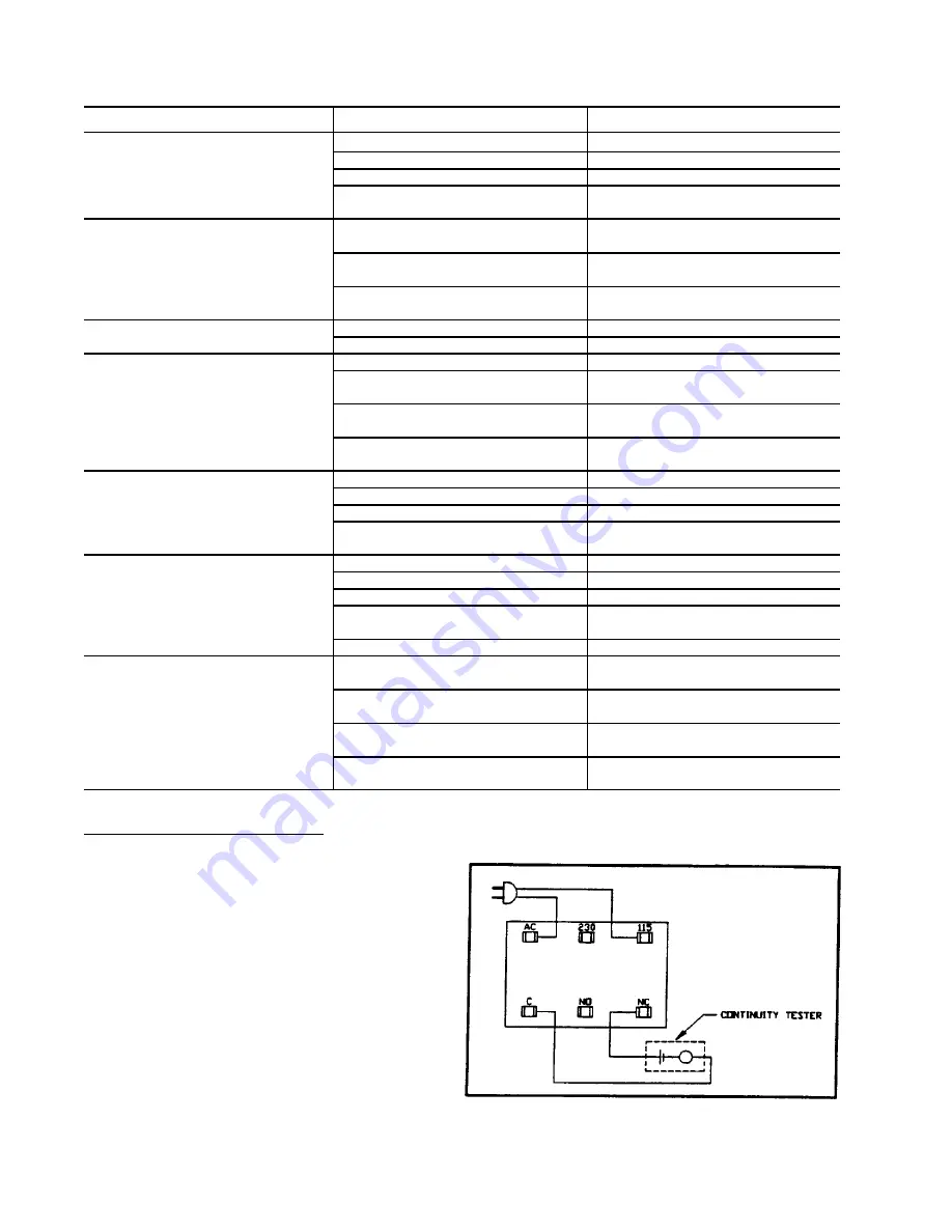
HOW TO CHECK TIMER
1. Connect either 115V or 230V to the input of
the timer as shown.
2. Connect continuity light or OHM meter
between the common and the normally closed
connectors on the timer as shown. The light
should glow (there should be continuity).
3. If timer is set for maximum time, light should
be out in 90 seconds. If time is less than 90
seconds at maximum setting, make sure the
dip switches on the FG-453 are set with 3 and
4 on and the rest off. If light does not go
out, timer is bad.
Содержание FINTUNMAN67
Страница 3: ...Page 3...
Страница 6: ...Page 6...
Страница 18: ...Page 18...
Страница 22: ...Page 22...
Страница 28: ...Page 28...
Страница 30: ...Page 30...
Страница 32: ...Page 32...
Страница 34: ...Page 34...
Страница 39: ...Page 39...
Страница 40: ...Page 40...
Страница 41: ...Page 41...

