Installing and Cabling the Displays
Page 74
© 2015 Cisco Systems, Inc. All rights reserved.
1
CAUTION: Use care and wear gloves when mounting the displays - the vertical outer edge of the
displays has a sharp edge that can cause injury if the display slides through your hands.
NOTE: Display assembly is different than the TX or CTS immersive systems, please read this section
carefully before installation and follow all steps in the correct order.
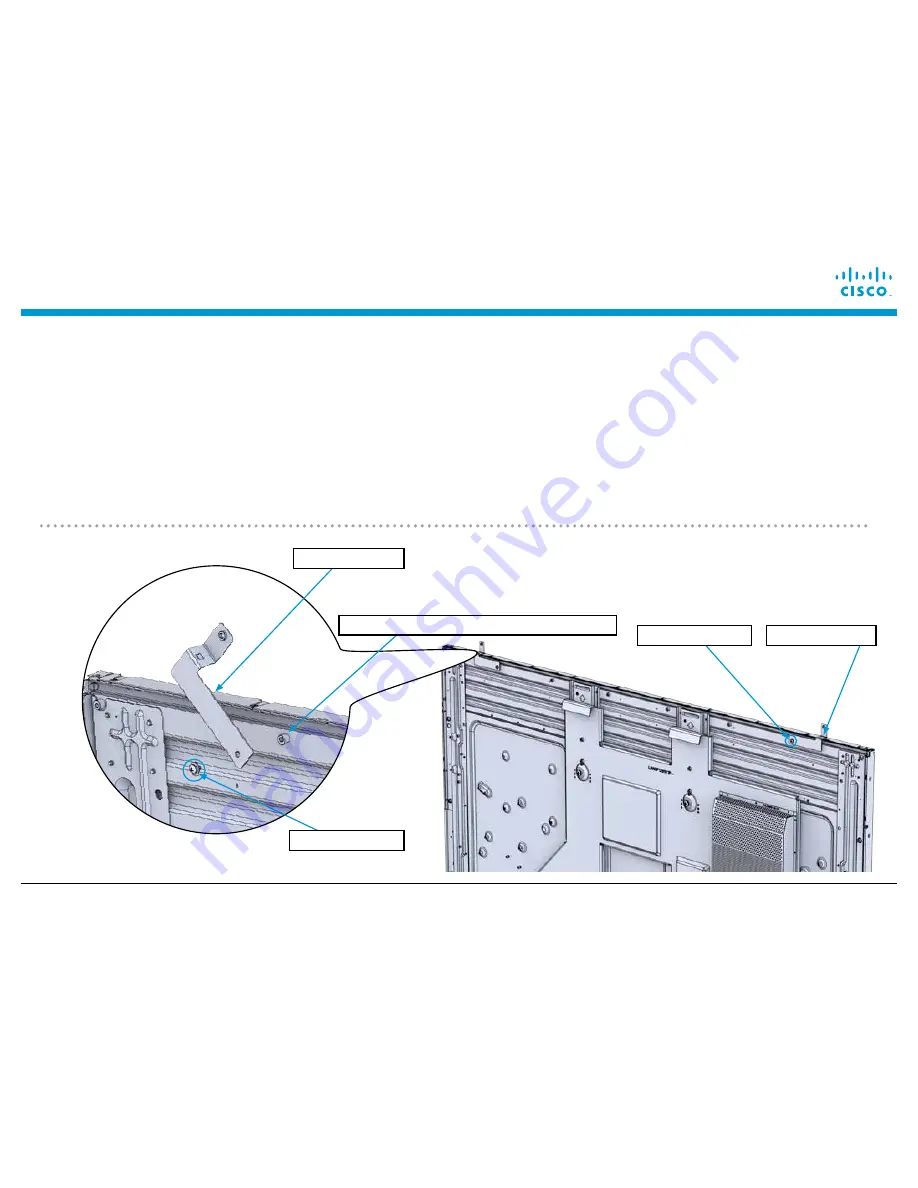
Attach the Z-clips to the top of the displays. 700-46232-xx goes on the left side (when viewed from the
FRONT of the display) and 700-46233-xx goes on the right.
a)
insert the 1x M4 X 6mm screw 69-2625-xx
into the bracket finger-tight,
b)
peel off the adhesive tape backing on the bracket,
c)
press the bracket to the
display, and
d)
tighten the 69-2625-xx screw with a #2 Phillips screwdriver.
e)
Repeat for all three displays.
700-46233-xx
700-46232-xx
1x 69-2625-xx
1x 69-2625-xx
Install on this standoff (2nd from end)
Содержание TelePresence IX5000
Страница 69: ...Installing Endpoint Structure Cables 2015 Cisco Systems Inc All rights reserved Page 69 Codec and cable runner ...
Страница 71: ...Installing Endpoint Structure Cables 2015 Cisco Systems Inc All rights reserved Page 71 ...
Страница 72: ...Installing Endpoint Structure Cables Page 72 2015 Cisco Systems Inc All rights reserved ...
Страница 137: ...Installing the Second Row Table IX5200 Only 2015 Cisco Systems Inc All rights reserved Page 137 Cable Routing Left ...
Страница 138: ...Installing the Second Row Table IX5200 Only Page 138 2015 Cisco Systems Inc All rights reserved Cable Routing Center ...
Страница 139: ...Installing the Second Row Table IX5200 Only 2015 Cisco Systems Inc All rights reserved Page 139 Cable Routing Right ...
Страница 185: ...Cable Routing Diagrams 2015 Cisco Systems Inc All rights reserved Page 185 ...
Страница 186: ...Cable Routing Diagrams Page 186 2015 Cisco Systems Inc All rights reserved ...


