


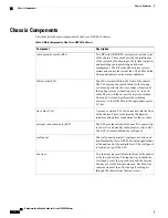


Card cages (2) each
containing:
•
8 LC slots
•
2 FC slots (in
center)
•
1 RP slot (at side)
5
External connection unit
(ECU)
•
Craft panel is
attached on top of
the ECU (not
shown, see
2: Partial Chassis
View with Craft
Panel, on page 5
)
•
Air outlet is on back
2
Air inlet
6
Fan trays (2)
3
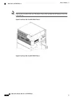
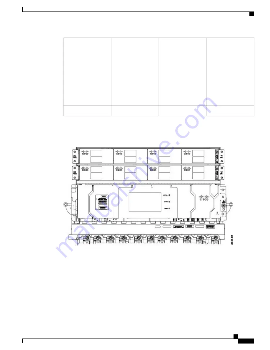
This figure shows the partial chassis view with craft panel.
Figure 2: Partial Chassis View with Craft Panel
The following figures show partial rear views of the Cisco NCS 4016 chassis.
Hardware Installation Guide for Cisco NCS 4000 Series
5
Chassis Overview
About the Cisco NCS 4016 Chassis
Содержание NCS 4000 Series
Страница 10: ...Hardware Installation Guide for Cisco NCS 4000 Series x Contents ...
Страница 70: ...Hardware Installation Guide for Cisco NCS 4000 Series 50 Installing Power Components Powering On the Chassis ...
Страница 162: ...Hardware Installation Guide for Cisco NCS 4000 Series 142 System Product IDs Accessory Product IDs ...
Страница 168: ...Hardware Installation Guide for Cisco NCS 4000 Series 148 Installation Roadmap for NCS 4009 Installation Roadmap ...
Страница 292: ...Hardware Installation Guide for Cisco NCS 4000 Series 272 System Product IDs Accessory Product IDs ...


