


4 ciscoBus Token Ring Card and Applique Installation and Upgrade Instructions
Product Descriptions
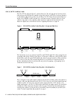
CSC-C2CTR Interface Card
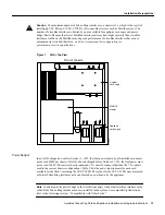
The CSC-C2CTR, shown in Figure 2, contains four ports. The card supports two interfaces when
used with one APP-LTR2 and four interfaces when used with two APP-LTR2s. Each port (interface)
is individually configured to operate at 4 or 16 Mbps. The C2CTR-specific microcode (firmware)
resides on an EPROM in socket position U98, which may need to be replaced when the system
software is upgraded or when operating enhancements are implemented. Instructions for the
microcode upgrade can be found in the section “Upgrading Microcode” on page 34.
Figure 2
CSC-C2CTR ciscoBus Token Ring Card—Component-Side View
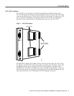
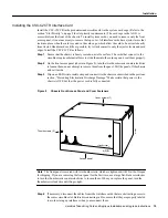
The four interface ports are numbered from left to right TR 0 through TR 3 when viewing the card
as installed in the system card cage. (See Figure 3.) Each port is connected to an APP-LTR2 with an
internal ribbon cable. Four green LEDs indicate the status of each port (interface). When an interface
is up, or active in the ring, the corresponding LED is on. The LED is off when the interface is
inactive, administratively down, not internally connected to the applique, or the applique is not
externally connected to the ring.
Figure 3
CSC-C2CTR ciscoBus Token Ring Card—Front-Edge View
The C2 designator in the product number indicates that the CSC-C2CTR card must be installed in
an AGS+ with a ciscoBus II controller card (CSC-CCTL2). The CSC-C2CTR can be installed in any
available ciscoBus slot except the center slot, which contains the CSC-CCTL2. However, for
optimum performance, the CSC-C2CTR should be installed in the highest-priority slot available in
accordance with the slot priority scheme described on page 9. Instructions for determining your
current system software version and the type of ciscoBus controller installed are provided in the
section “System Compatibility Requirements” on page 6.
U98
H1537a
TR 0
Microcode
EPROM
TR 1
TR 2
TR 3
LEDs
(4)
Port 0
LED
H1206a
Port 0
Port 1
LED
Port 2
LED
Port 3
LED
Port 1
Port 2
Port 3
Interface ports