26 ciscoBus Token Ring Card and Applique Installation and Upgrade Instructions
Installation
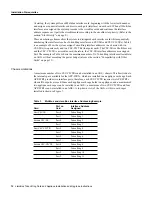
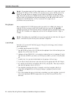
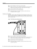
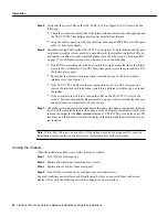
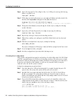
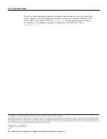
Figure 13
CSC/4 Processor Card LED Indicators—Front-Edge View
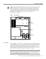
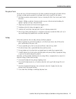
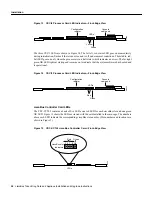
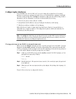
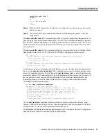
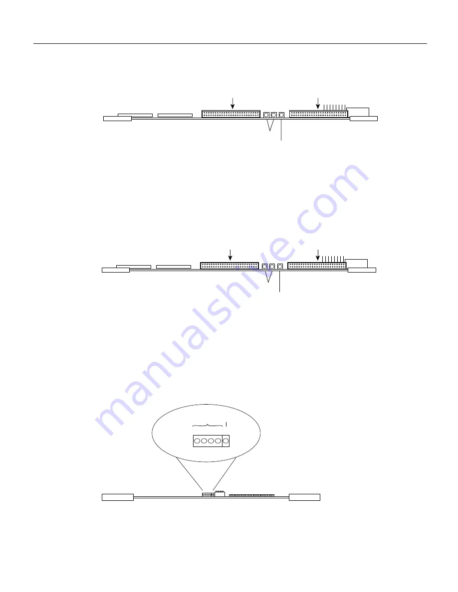
The three CSC/3 LEDs are shown in Figure 14. The far left, red, status LED goes on momentarily
during initialization, flashes if there is an error, and is off under normal conditions. The middle, red,
halt LED goes on only when the processor is in a halt state (which indicates an error). The far right
green OK LED lights at startup and remains on to indicate that the system software has booted and
is operational.
Figure 14
CSC/3 Processor Card LED Indicators—Front-Edge View
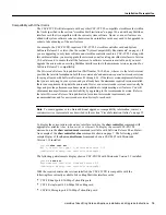
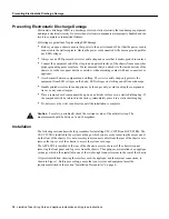
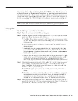
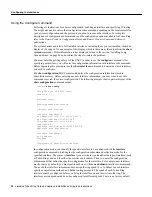
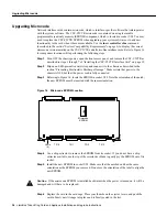
ciscoBus Controller Card LEDs
The CSC-CCTL2 contains a bank of five LEDs, one red LED for each ciscoBus slot and one green
OK LED. Figure 15 shows the LEDs as viewed with the card installed in the card cage. The numbers
above each LED indicate the corresponding ciscoBus slot number. (Slot numbers and locations are
shown in Figure 5.)
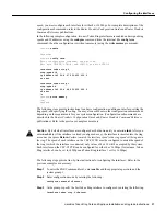
Figure 15
CSC-CCTL2 ciscoBus Controller Card—Front-Edge View
Console
cable port
Configuration
register
LEDs
Yellow
Green
H1083a
LEDs
Red
Green
H1082a
Console
cable port
Configuration
register
LEDs
H1205a
3 2 1 0
Red
ciscoBus slot
indicators
Green
OK