
32 ciscoBus Token Ring Card and Applique Installation and Upgrade Instructions
Configuring the Interfaces
Step 4
Specify the ring speed for Token Ring 0, either 4 or 16 (Mbps), by entering the following
(where n is either
4
or
16
):
ring-speed
n <Return>
Step 5
If IP routing is enabled on the system, you can assign an IP address and subnet mask to the
interface with the ip address configuration subcommand as follows:
ip address 111.111.111.111 255.255.255.0 <Return>
(where 111.111.111.111 represents whatever address you assign to this interface)
Step 6
Change the default shutdown state and bring the interface up by entering the following:
no shut <Return>
Step 7
Specify the next Token Ring interface to configure by entering the following:
interface token ring 1 <Return>
Step 8
Repeat steps 3 through 6 for each new Token Ring interface.
Step 9
When all new interfaces are configured, enter Ctrl - Z (hold the Control key down and
press z).
Step 10
Write the new configuration to memory by entering the following:
write memory <Return>
The system will display an OK message to indicate that the configuration has been stored.
Step 11
To exit configuration mode, enter quit.
Step 12
Check the configuration as described in the following section.
Checking the Configuration
After you have configured the ring speed of each interface, check the LEDs on the CSC-C2CTR and
use EXEC command displays to verify the new Token Ring interfaces. When the system is started,
the interface cards query the appliques for interface information. If an applique is not connected to
its interface card when the system initializes, it will be not be recognized until it is properly
connected to the card, and the system is restarted.
To check the configuration, proceed as follows:
Step 1
Turn the system power OFF, wait approximately five seconds, then turn the power ON
again to reboot the system. (The system will beep when it has booted.)
Step 2
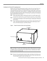
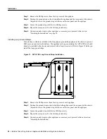
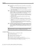
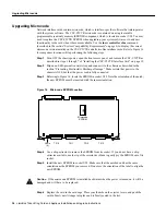
Open the front access panel and check the LEDs on the CSC-C2CTR. Two LEDs are
located on each side of the card, numbered 0 through 3 from left to right as shown in
Figure 3. Each LED goes on to indicate that the corresponding interface is active. The LED
for each active interface should be on.
Step 3
If any of the LEDs indicate that an interface is not active (but should be), return to the
configuration mode as described in steps 1 through 3 on page 31. Enter the interface unit
address, then enter no shut as shown in the following example:
router# config term
Enter configuration commands, one per line.
Edit with DELETE, CTRL/W, and CTRL/U; end with CTRL/Z