24 Installing and Upgrading the CSC-C2FCIT FDDI Card and Appliques
Testing the Installation
Reading the LED Indicators
Two separate sets of LEDs provide status about the installation: those on the CCTL2 card and those
on the FDDI applique. The LEDs on the CCTL2 card will verify the presence (and correct
installation) of the C2FCIT cards in the ciscoBus backplane, while the LEDs on the applique report
the state of the FDDI interfaces.
CSC-CCTL2 Card LED Indicators
The C2FCIT card contains no LEDs or indicators. The LEDs on the CCTL2 card indicate when a
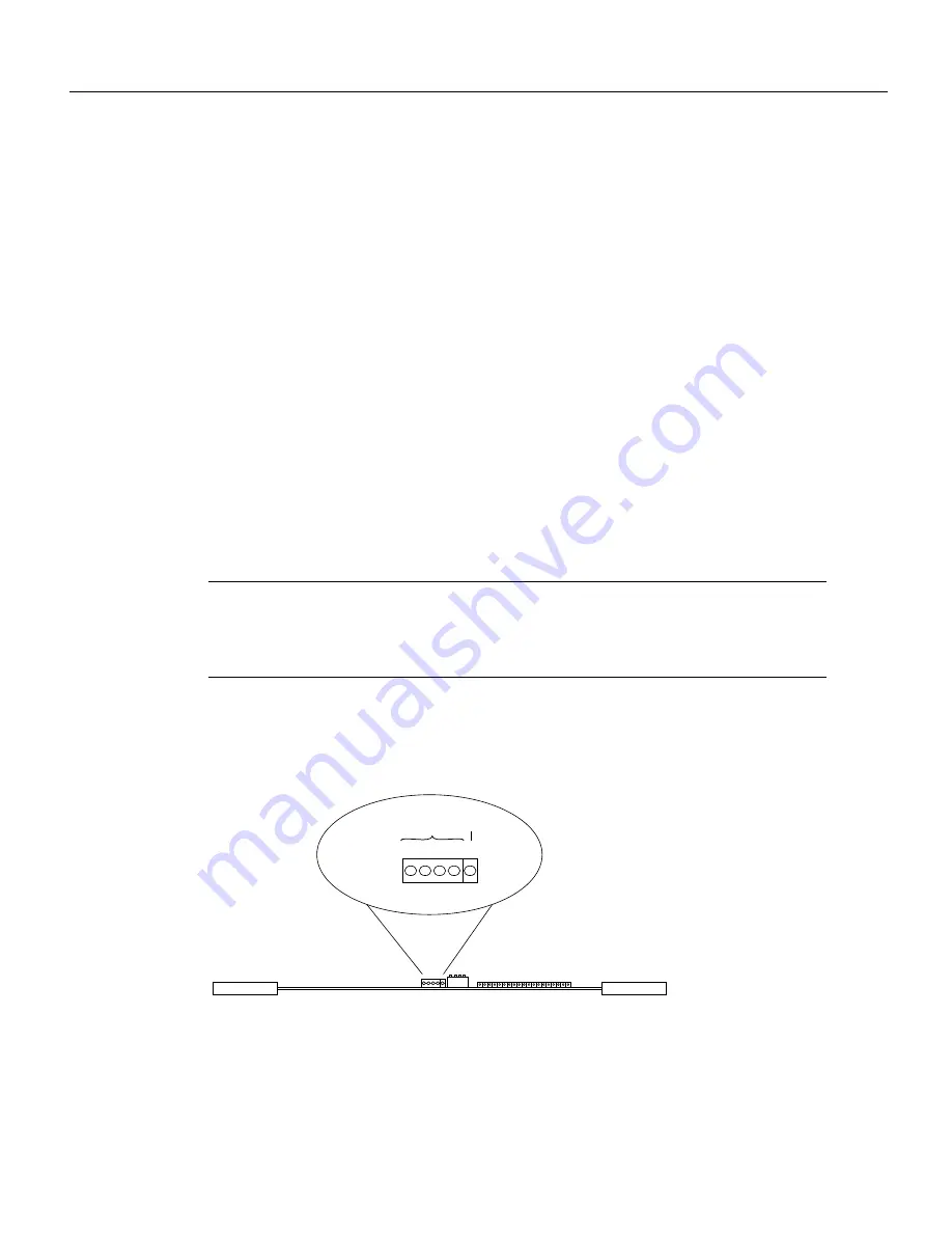
ciscoBus interface is present in a ciscoBus slot. The front edge of the CCTL2 card contains a bank
of five LEDs as shown in Figure 16, one red LED for each interface slot in the ciscoBus, and a green
(boot) LED to indicate a successful boot procedure.
One red LED will be on for each correctly connected ciscoBus card using the correct version of
microcode. It will not be on if the card is incorrectly connected or if the microcode version is wrong.
On power up, all five LEDs are on, indicating that the CCTL2 card is active. Once the system is
booted, and the ciscoBus controller card microcode has completed its discovery phase, the only red
LEDs will be those on that indicate the presence of a card in a ciscoBus slot. The green LED is also
on to indicate a successful boot operation. Figure 16 illustrates which LED will be on to indicate the
presence of a card in the ciscoBus slot. The numbers above each LED (3, 2, 1, and0 from left to right)
indicate the ciscoBus slot number assigned to that LED.
Note
Verify that the red LED for the ciscoBus slot in which your C2FCIT card is installed comes
on and remains on. If it does not, check the C2FCIT card to ensure that it is firmly seated in the
ciscoBus and Multibus backplanes. When the card is installed correctly, the ejector levers are firmly
in place.
Figure 16
CCTL2 Card LED Indicators—Front-Edge View
LEDs
H1205a
3 2 1 0
Red
ciscoBus slot
indicators
Green
OK


