background image


xiii

Cisco 1900 Series Hardware Installation

OL-19084-02

Preface

Содержание 1905

Страница 1: ... Systems Inc 170 West Tasman Drive San Jose CA 95134 1706 USA http www cisco com Tel 408 526 4000 800 553 NETS 6387 Fax 408 527 0883 Cisco 1900 Series Integrated Services Router Hardware Installation Text Part Number OL 19084 03 ...

Страница 2: ...y of California Berkeley UCB as part of UCB s public domain version of the UNIX operating system All rights reserved Copyright 1981 Regents of the University of California NOTWITHSTANDING ANY OTHER WARRANTY HEREIN ALL DOCUMENT FILES AND SOFTWARE OF THESE SUPPLIERS ARE PROVIDED AS IS WITH ALL FAULTS CISCO AND THE ABOVE NAMED SUPPLIERS DISCLAIM ALL WARRANTIES EXPRESSED OR IMPLIED INCLUDING WITHOUT L...

Страница 3: ...ety Warnings for Finland Norway and Sweden 1 2 Chassis Views 1 2 Hardware Features 1 5 Product Serial Number Location 1 6 Cisco Product Identification Tool 1 7 Built In Interfaces 1 7 Removable Interchangeable and Optional Modules 1 8 Memory 1 9 LED Indicators 1 10 Chassis Ventilation 1 12 Real Time Clock 1 12 Chassis Security 1 12 Wireless LAN Connectivity 1 12 Baud Reset Button 1 13 Interface Nu...

Страница 4: ...nsiderations 3 1 About Console and Auxiliary Ports 3 1 Console Port Connections 3 1 EIA TIA 232 Port 3 2 USB Serial Console 3 2 Auxiliary Port Connections 3 3 Preparing to Connect to a Network 3 3 Ethernet Connections 3 3 Serial Connections 3 3 About Serial Connections 3 4 Configuring Serial Connections 3 4 Serial DTE or DCE Devices 3 4 Signaling Standards Supported 3 4 Transmission Speeds and Dis...

Страница 5: ...er 4 17 Installing the Cisco Microsoft Windows 2000 USB Driver 4 17 Installing the Cisco Microsoft Windows Vista USB Driver 4 18 Uninstalling the Cisco USB Driver 4 18 Uninstalling the Cisco Microsoft Windows XP and 2000 USB Driver 4 18 Using the Add Remove Programs Utility 4 18 Using the Setup exe Program 4 19 Uninstalling the Cisco Microsoft Windows Vista USB Driver 4 19 Connecting to the Auxili...

Страница 6: ...ute or Gateway of Last Resort 5 14 Configuring IP Routing and IP Protocols 5 14 Gateway of Last Resort 5 15 Configuring Virtual Terminal Lines for Remote Console Access 5 17 Configuring the Auxiliary Line 5 18 Verifying Network Connectivity 5 19 Saving Your Router Configuration 5 21 Saving Backup Copies of Configuration and System Image 5 21 Verifying the Initial Configuration 5 23 C H A P T E R 6...

Страница 7: ...tall connect and perform initial configuration for the Cisco 1900 series Integrated Services Routers ISRs Some information may not apply to your particular router model For warranty service and support information see the Cisco Warranty Terms section in the Readme First for the Cisco 1900 Series Integrated Services Routers document that was shipped with your router Audience This documentation is d...

Страница 8: ...for the Router Describes how to activate a software package or feature and perform a license transfer Convention Indication bold font Commands and keywords and user entered text appear in bold font italic font Document titles new or emphasized terms and arguments for which you supply values are in italic font Elements in square brackets are optional x y z Required alternative keywords are grouped ...

Страница 9: ...71 SAVE THESE INSTRUCTIONS Waarschuwing BELANGRIJKE VEILIGHEIDSINSTRUCTIES Dit waarschuwingssymbool betekent gevaar U verkeert in een situatie die lichamelijk letsel kan veroorzaken Voordat u aan enige apparatuur gaat werken dient u zich bewust te zijn van de bij elektrische schakelingen betrokken risico s en dient u op de hoogte te zijn van de standaard praktijken om ongelukken te voorkomen Gebru...

Страница 10: ...bolo di avvertenza indica un pericolo La situazione potrebbe causare infortuni alle persone Prima di intervenire su qualsiasi apparecchiatura occorre essere al corrente dei pericoli relativi ai circuiti elettrici e conoscere le procedure standard per la prevenzione di incidenti Utilizzare il numero di istruzione presente alla fine di ciascuna avvertenza per individuare le traduzioni delle avverten...

Страница 11: ...ero que le ayudará a encontrar el texto traducido en el apartado de traducciones que acompaña a este dispositivo GUARDE ESTAS INSTRUCCIONES Varning VIKTIGA SÄKERHETSANVISNINGAR Denna varningssignal signalerar fara Du befinner dig i en situation som kan leda till personskada Innan du utför arbete på någon utrustning måste du vara medveten om farorna med elkretsar och känna till vanliga förfaranden ...

Страница 12: ...rnecido ao final de cada aviso para localizar sua tradução nos avisos de segurança traduzidos que acompanham o dispositivo GUARDE ESTAS INSTRUÇÕES Advarsel VIGTIGE SIKKERHEDSANVISNINGER Dette advarselssymbol betyder fare Du befinder dig i en situation med risiko for legemesbeskadigelse Før du begynder arbejde på udstyr skal du være opmærksom på de involverede risici der er ved elektriske kredsløb ...

Страница 13: ...xiii Cisco 1900 Series Hardware Installation OL 19084 02 Preface ...

Страница 14: ...s not limited to CISCO designated products Statement 371 Warning There is the danger of explosion if the battery is replaced incorrectly Replace the battery only with the same or equivalent type recommended by the manufacturer Dispose of used batteries according to the manufacturer s instructions Statement 1015 Warning Do not use this product near water for example near a bath tub wash bowl kitche...

Страница 15: ...erview of Cisco Network Modules and Service Modules for Cisco Access Routers Installing Cisco Network Modules and Service Modules in Cisco Access Routers Cisco Interface Cards for Cisco Access Routers Installing Cisco Interface Cards in Cisco Access Routers Installing Replacing and Upgrading Components in Cisco Modular Access Routers and Integrated Services Routers Declarations of Conformity and R...

Страница 16: ...es simultaneously and to change case sensitivity and other options Adobe Reader s online help has more information about how to search PDF documents Obtaining Documentation and Submitting a Service Request For information on obtaining documentation submitting a service request and gathering additional information see the monthly What s New in Cisco Product Documentation which also lists all new an...

Страница 17: ... USB devices and a USB mini Type B serial console port is available in addition to the RJ 45 console connector This chapter provides an overview of the Cisco 1900 series routers and includes the following sections Safety Warnings page 1 1 Chassis Views page 1 2 Hardware Features page 1 5 Interface Numbering page 1 13 Specifications page 1 14 Regulatory Compliance page 1 18 Safety Warnings Warning ...

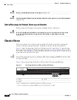
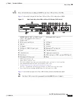
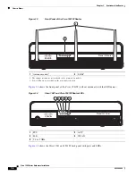
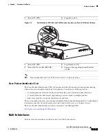
Страница 18: ...ocations of the power and signal interfaces the interface card slots and the status indicators Figure 1 1 shows the front panel of the Cisco 1905 and Cisco 1921 router Figure 1 2 shows the back panel connectors on the Cisco 1905 and Cisco 1921 router Figure 1 3 shows the front panel of a Cisco 1941 wireless router and Figure 1 4 shows the LEDs of the Cisco 1941 router Figure 1 5 shows the back pan...

Страница 19: ...with a permanently installed interface card Only slot 1 Left is available 4 Only 1 EHWIC Gigabit Ethernet Switch can be installed in a 1905 or 1921 5 See Module Support on Cisco s Integrated Services Routers Generation 2 http cisco com en US prod collateral routers ps10538 aag_c07_563807 pdf for supported modules 2 EN Enable RJ 45 console 3 RJ 45 serial console port 4 AUX port 5 GE 0 1 6 GE 0 0 7 ...

Страница 20: ...names Figure 1 4 Cisco 1941 and Cisco 1941W Router LEDs Figure 1 5 shows the Cisco 1941 and 1941W back panel with ports and LEDs 1 Antenna mounts1 1 The antenna mounts are not available on the non wireless models 2 LEDs2 2 Some LEDs are not available on the non wireless models GHz SYS ACT POE WLAN 2 4 5 251372 1 2 Cisco 1900 Series 1 SYS 2 ACT 3 PoE 4 WLAN 5 2 4 or 5 GHz GHz SYS ACT POE WLAN 2 4 5...

Страница 21: ...upport is for data only 2 See Module Support on Cisco s Integrated Services Routers Generation 2 http cisco com en US prod collateral routers ps10538 aag_c07_563807 pdf for supported modules 10 ISM3 or WLAN 3 Internal Service Module ISM 11 CF 0 12 CompactFlash 0 13 HWIC slot 1 EHWIC HWIC or WIC double wide4 4 The double wide slot can accommodate a single wide EHWIC HWIC WIC or VWIC data only on th...

Страница 22: ...and Cisco 1921 series routers is located on the bottom of the chassis See Figure 1 8 The serial number label for the Cisco 1940 series routers is located on the rear of the chassis on a pull out tab See Figure 1 8 Figure 1 6 Serial Number and CLEI Location on Cisco 1905 and Cisco 1921 Routers Figure 1 7 PID and Compliance Label on Cisco 1905 and Cisco 1921 Routers EN EN CONSOLE FLASH EHWIC 1 EHWIC...

Страница 23: ...he final results page making it easier to look up multiple products End of sale products are clearly identified in results lists The tool streamlines the process of locating serial number labels and identifying products Serial number information expedites the entitlement process and is important for access to support services The Cisco Product Identification tool can be accessed at the following U...

Страница 24: ...e internal power supply providing in line power 802 3af compliant Power over Ethernet PoE and Cisco standard inline power to optional integrated switch modules The Cisco 1905 and Cisco 1921 have an external feed for PoE See Figure 1 2 There are no user installable or replaceable modules on the Cisco 1905 or Cisco 1921 routers The chassis cover should never be removed Caution Power off the PoE befo...

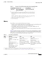
Страница 25: ...ility CompactFlash CF purchased from Cisco operate in Cisco 1900 series ISRs Legacy CF will not operate in these routers When legacy CF is inserted the following error message appears WARNING Unsupported compact flash detected Use of this card during normal operation can impact and severely degrade performance of the system Please use supported compact flash cards only Enhanced High Speed WAN Inte...

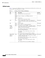
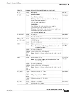
Страница 26: ...ont panel PoE Green PoE is available Front panel Amber Power supply is not supplying PoE power WLAN 2 4GHz Wireless Models Green On Radio is connected SSID1 is configured signal is being transmitted and client is associated but no data is being received or being transmitted Slow blinking Radio is connected SSID is configured and beacons are being transmitted Fast blinking Data is either being rece...

Страница 27: ... Initialized with error CF 1 Green Flash memory is busy Note Do not remove the CompactFlash memory card when this light is on Next to the CF1 slot Amber Initialized with error Blinking Green then turns off CompactFlash is ready for removal Note Remove the CompactFlash when the light turns off CF 0 Green Flash memory is busy Note Do not remove the CompactFlash memory card when this light is on Next...

Страница 28: ...t field replaceable Note If the lithium battery in a Cisco 1900 ISR should fail the router must be returned to Cisco for repair Although the battery is not intended to be field replaceable the following warning must be heeded Warning Dispose of used batteries according to the manufacturer s instructions Statement 1015 Chassis Security The chassis of the router is constructed with a KensingtonTM se...

Страница 29: ... individual interface port on a Cisco 1900 series router is identified by a number The Cisco 1900 series routers contains the following wide area network WAN and local area network LAN interface types Two onboard Gigabit Ethernet GE LAN interfaces Two slots in which you can install WICs VWICs data only and HWICs The Cisco 1905 comes with a factory installed EHWIC in the right slot The numbering fo...

Страница 30: ...ecifications for Cisco 1940 series routers Slot 0 EHWIC HWIC WIC 0 0 0 to 0 0 0 single wide Slot 1 EHWIC WIC VWIC 0 1 0 to 0 1 0 single or double wide Table 1 6 Interface Numbering continued Slot Number Slot Type Slot Numbering Range Table 1 7 Cisco 1905 and 1921 Series Router Specifications1 Description Specification Physical Dimensions without rubber feet H x W x D 1 75 in x 13 5 in x 11 5 in 4 ...

Страница 31: ...vation 32 to 104 F 0 to 40 C Operating temperature up to 9843 ft 3000 m elevation 32 77 F 0 25 C Operating altitude maximum 10 000 ft 3000 m Transportation and Storage Environment Nonoperating temperature 40 to 158 F 40 to 70 C Nonoperating humidity 5 to 95 RH Nonoperating altitude 15 000 ft 4570 m Acoustic Sound Pressure Typ Max 32 9 58 3 dBA Sound Power Typ Max 41 9 67 2 dBA Regulatory Electroma...

Страница 32: ...onal information 2 Rack unit RU 3 480 Mb s individually bandwidth is shared when both are used 4 Auto MDIX auto media dependent interface cross over Table 1 7 Cisco 1905 and 1921 Series Router Specifications1 Description Specification Table 1 8 Cisco 1940 Series Router Specifications1 Description Specification Physical Dimensions without rubber feet H x W x D 3 5 x 13 5 x 11 5 in 8 9 x 34 3 x 29 2...

Страница 33: ...0 to 85 RH Operating temperature up to 5906 ft 1800 m elevation 32 to 104 F 0 to 40 C Operating temperature up to 9843 ft 3000 m elevation 32 77 F 0 25 C Operating altitude maximum 10 000 ft 3000 m Transportation and Storage Environment Nonoperating temperature 40 to 158 F 40 to 70 C Nonoperating humidity 5 to 95 RH Nonoperating altitude 15 000 ft 4570 m Acoustic Sound Pressure Typ Max 26 46 dBA S...

Страница 34: ...gulatory Compliance and Safety Information for Cisco 1900 Series Routers Telecom TIA EIA IS 968 CS 03 ANSI T1 101 ITU T G 823 G 824 IEEE 802 3 RTTE Directive For detailed compliance information see Regulatory Compliance and Safety Information for Cisco 1900 Series Routers 1 Refer to the Cisco 1900 Series Integrated Services Routers Data Sheet for additional information 2 Rack unit RU 3 480 Mb s in...

Страница 35: ...ry Compliance and Safety Information for Cisco 1900 Series Routers document that accompanies your router Safety Recommendations General Guidelines page 2 1 Safety with Electricity page 2 2 Preventing Electrostatic Discharge Damage page 2 3 General Guidelines Follow these guidelines to ensure general safety Keep the chassis area clear and dust free during and after installation If you remove the ch...

Страница 36: ...dled according to all national laws and regulations Statement 1040 Safety with Electricity Follow these guidelines when working on equipment powered by electricity Warning Do not work on the system or connect or disconnect cables during periods of lightning activity Statement 1001 Warning Read the installation instructions before connecting the system to the power source Statement 1004 Warning Whe...

Страница 37: ...cuitry ESD can occur if electronic printed circuit cards are improperly handled and can cause complete or intermittent failures Always follow ESD prevention procedures when removing and replacing modules Ensure that the router chassis is electrically connected to earth ground Wear an ESD preventive wrist strap ensuring that it makes good skin contact Connect the clip to an unpainted surface of the...

Страница 38: ...guration section on page 2 4 to help avoid equipment failures and reduce the possibility of environmentally caused shutdowns If you are currently experiencing shutdowns or an unusually high number of errors with your existing equipment these precautions may help you isolate the cause of the failures and prevent future problems Site Configuration The following precautions will help you plan an acce...

Страница 39: ... install it If the final installation site will not be ready for some time keep the chassis in its shipping container to prevent accidental damage When you are ready to install the router proceed with unpacking it The router cables publications and any optional equipment that you ordered may be shipped in more than one container Inspect all items for shipping damage If anything appears to be damag...

Страница 40: ...nance and expansion history A Site Log might include the following events Installation of network modules Removal or replacement of network modules and other upgrades Configuration changes Maintenance schedules and requirements Maintenance procedures performed Intermittent problems Comments and notes Router quick start guide received Cisco Regulatory Compliance and Safety Information Roadmap docum...

Страница 41: ... to earth ground In addition depending on the type of modules that you plan to use you might need the following equipment to connect a port to an external network Cables for connection to WAN and LAN ports dependent on configuration Note For more information on cable specifications refer to Cisco Modular Access Router Cable Specifications Ethernet hub or PC with a network interface card for connec...

Страница 42: ...2 8 Cisco 1900 Series Hardware Installation OL 19084 02 Chapter 2 Preparing for Router Installation Required Tools and Equipment for Installation and Maintenance ...

Страница 43: ...abling information to consider before connecting the router to a console terminal or modem The main difference between the console and auxiliary ports is that the auxiliary port supports flow control whereas the console port does not Flow control paces the transmission of data between a sending device and a receiving device Flow control ensures that the receiving device can absorb the data sent to...

Страница 44: ...rol The default parameters for the console port are 9600 baud 8 data bits no parity and 1 stop bit The console port does not support mode control For detailed information about installing a console terminal see the Connecting to the Console Port with Microsoft Windows section on page 4 14 For operation with Microsoft Windows the Cisco Windows USB Console Driver must be installed on any PC connecte...

Страница 45: ...nnection considerations for several types of network interfaces Ethernet Connections page 3 3 Serial Connections page 3 3 ISDN BRI Connections page 3 6 CSU DSU Connections page 3 6 Refer to Cisco Modular Access Router Cable Specifications for more information about network connections and interfaces Ethernet Connections The IEEE has established Ethernet as standard IEEE 802 3 The Cisco 1941 Ethern...

Страница 46: ... Serial DTE or DCE Devices A device that communicates over a synchronous serial interface is either a DTE or DCE device A DCE device provides a clock signal that paces the communications between the device and the router A DTE device does not provide a clock signal DTE devices usually connect to DCE devices The documentation for the device should indicate whether it is a DTE or DCE device Some dev...

Страница 47: ...rally the slower the data rate the greater the distance All serial signals are subject to distance limits beyond which a signal is significantly degraded or is completely lost Table 3 2 lists the recommended maximum speeds and distances for each serial interface type however you might get good results at speeds and distances greater than those listed if you understand the electrical problems that ...

Страница 48: ...rained engineers Statement 23 Warning Hazardous network voltages are present in WAN ports regardless of whether power to the unit is OFF or ON To avoid electric shock use caution when working near WAN ports When detaching cables detach the end away from the unit first Statement 1026 Use a BRI cable not included to connect the BRI WIC directly to an ISDN Table 3 3 lists the specifications for ISDN ...

Страница 49: ... routers About Modules page 4 1 Safety Warnings page 4 2 Setting Up the Chassis page 4 3 Installing the Chassis Ground Connection page 4 9 Connecting WAN and LAN Cables page 4 11 Connecting to a Console Terminal or Modem page 4 14 Installing the Cisco Microsoft Windows USB Device Driver page 4 17 Uninstalling the Cisco USB Driver page 4 18 Connecting to the Auxiliary Port page 4 20 Connecting Powe...

Страница 50: ... Cisco 1900 Series ISRs Safety Warnings Note To see translations of the warnings that appear in this publication refer to the Regulatory Compliance and Safety Information for Cisco 1900 Series Routers document that accompanies your router Warning IMPORTANT SAFETY INSTRUCTIONS This warning symbol means danger You are in a situation that could cause bodily injury Before you work on any equipment be ...

Страница 51: ...top and can also be mounted on a wall Select the setup that best meets the needs of your network These setups are described in the following sections Chassis Airflow Diagram page 4 3 Setting the Chassis on a Desktop page 4 4 Chassis Grounding page 4 4 Wall Mounting the Chassis page 4 4 Rack Mounting the Chassis page 4 7 Caution The front panel bezel must not be removed from the Cisco 1900 series r...

Страница 52: ...port the weight of the unit Statement 1032 Caution Do not place anything on top of the router that weighs more than 10 pounds 4 5 kilograms Excessive weight on top of the router could damage the chassis Chassis Grounding After the router has been installed you must connect the chassis to a reliable earth ground For the chassis ground connection procedure see the Installing the Chassis Ground Conne...

Страница 53: ...ws We recommend using pan head or round head screws Caution The screws must go into a wall stud wood or a wall anchor of the appropriate type for the wall Screws into drywall are not sufficient to mount the router Figure 4 3 shows the wall mounting features on the Cisco 1905 and Cisco 1921 routers Figure 4 3 Wall Mounting Features on the Cisco 1905 and Cisco 1921 Routers 1 Wall screws 2 8 inches 2...

Страница 54: ... The screws should protrude 0 25 inch 0 6 centimeter from the surface of the wall Caution If you install the screws in drywall use hollow wall anchors 1 8 inch by 5 16 inch to secure the screws If the screws are not properly anchored the strain of the cables connected to the router back panel could pull the router from the wall Step 2 Remove the rubber feet from the router 1 Wall screws 2 5 inches...

Страница 55: ...he router in the following ways Front mounting Brackets attached at the front of the chassis with the front panel facing forward Back mounting Brackets attached at the back of the chassis with the back panel facing forward Note The rubber feet need to be removed for rack mounting Attaching Rack Mount Brackets to Cisco 1900 Series Routers Use four of the supplied number 8 Phillips screws to attach ...

Страница 56: ...des of the router with the back panel forward Figure 4 6 Bracket Installation for Back Mounting the Cisco 1905 and Cisco 1921 ISRs Figure 4 7 shows how to attach the brackets to the sides of the router with the front panel forward Figure 4 7 Bracket Installation for Front Mounting the Cisco 1940 Series ISR 253712 Cisco 2900 Series SYS ACT POE 253713 Cisco 1900 Series SYS ACT POE DO NOT REMOVE DURI...

Страница 57: ... Never defeat the ground conductor or operate the equipment in the absence of a suitably installed ground conductor Contact the appropriate electrical inspection authority or an electrician if you are uncertain that suitable grounding is available Statement 1024 Warning This equipment needs to be grounded Use a green and yellow 12 to 14 AWG ground wire to connect the host to earth ground during no...

Страница 58: ...ovided on the rear panel of the router The crimping tool should be one that is recommended by the ring lug terminal manufacturer Step 3 Attach the ring terminal to the chassis The attachment points are shown in Figure 4 10 and Figure 4 11 Use a number 2 Phillips screwdriver and the screw supplied with the ground lug Tighten the screw to a torque of 8 to 10 in lb 0 9 to 1 1 N m Figure 4 10 Chassis ...

Страница 59: ...uring periods of lightning activity Statement 1001 Warning Voice over IP VoIP service and the emergency calling service do not function if power fails or is disrupted After power is restored you might have to reset or reconfigure equipment to regain access to VoIP and the emergency calling service In the USA this emergency number is 911 You need to be aware of the emergency number in your country ...

Страница 60: ... directly with optical instruments Statement 1051 Warning Do not locate the antenna near overhead power lines or other electric light or power circuits or where it can come into contact with such circuits When installing the antenna take extreme care not to come into contact with such circuits because they may cause serious injury or death For proper installation and grounding of the antenna pleas...

Страница 61: ...l 1T 60 pin D sub blue CSU DSU and serial network or equipment Cisco serial transition cable that matches the signaling protocol EIA TIA 232 EIA TIA 449 V 35 X 21 or EIA TIA 530 and the serial port operating mode DTE or DCE Refer to Cisco Modular Access Router Cable Specifications for information about selecting these cables Cisco Smart serial 2T Cisco Smart compact connector blue CSU DSU and seri...

Страница 62: ... Console section on page 3 2 for port details and the Specifications section on page 1 14 Console cable EIA RJ 45 to DB 9 Modem adapter DB 9 to DB 25 Note The first time a Windows based PC is connected to the router a USB device driver must be installed See the Installing the Cisco Microsoft Windows USB Device Driver section on page 4 17 This section describes how to connect a console terminal or ...

Страница 63: ... on a Windows based PC you must install the Windows USB driver See the Installing the Cisco Microsoft Windows USB Device Driver section on page 4 17 Note You must use either the USB port or the RJ 45 port but not both simultaneously See the USB Serial Console section on page 3 2 When the USB port is used it takes priority over the RJ 45 EIA port Figure 4 12 Connecting the Console Cable to the Rout...

Страница 64: ...o find the OS X USB port number macbook user cd dev macbook user ls ltr dev usb crw rw rw 1 root wheel 9 66 Apr 1 16 46 tty usbmodem1a21 DT ullals macbook dev user Step 4 Connect to the USB port with the following command followed by the router USB port speed macbook user screen dev tty usbmodem1a21 9600 Step 5 To disconnect the OS X USB console from the Terminal window enter Ctrl a followed by Ct...

Страница 65: ...sco com support downloads go Redirect x mdfid 268437899 Procedure Step 1 Unzip the file cisco_usbconsole_driver_X_X zip where X is a revision number Step 2 Double click the file setup exe Step 3 The Cisco Virtual Com InstallShield Wizard begins Click Next Step 4 The Ready to Install the Program window appears Click Install Step 5 The InstallShield Wizard Completed window appears Click Finish Step ...

Страница 66: ...program to proceed Step 5 The InstallShield Wizard Completed window appears Click Finish Step 6 Connect the USB cable to the PC and router USB console ports See Table 4 1 on page 4 15 The EN LED for the USB console port turns green and within a few moments a pop up window stating Installing device driver software appears The USB console is ready for use Uninstalling the Cisco USB Driver Uninstalli...

Страница 67: ...Program Maintenance window appears select the Remove radio button Click Next Step 4 When the Remove the Program window appears click Remove Step 5 When the InstallShield Wizard Completed window appears click Finish Uninstalling the Cisco Microsoft Windows Vista USB Driver Before You Begin Disconnect the router console terminal before uninstalling the driver Procedure Step 1 Run the setup exe progr...

Страница 68: ...e black AUX port on the router See Figure 4 13 Figure 4 13 Connecting a Modem to the Router Step 2 Connect the DB 9 end of the console cable to the DB 9 end of the modem adapter Step 3 Connect the DB 25 end of the modem adapter to the modem Step 4 Make sure that your modem and the router auxiliary port are configured for the same transmission speed up to 115200 bps is supported and for mode contro...

Страница 69: ...nt Statement 1030 Note The installation must comply with all required electrical codes applicable at the installation site Connecting to AC Power If your router uses AC power connect it to a 15A 120VAC 10A 240VAC circuit with overcurrent protection Note The input voltage tolerance limits for AC power are 85 and 264 VAC Note This product requires surge protection to be provided as part of the build...

Страница 70: ...ations Statement 1045 Warning This product relies on the building s installation for short circuit over current protection Ensure that the protective device is rated not greater than 60VDC 20A Statement 1005 Warning Only trained and qualified personnel should be allowed to install replace or service this equipment Statement 1030 Warning Use copper conductors only Statement 1025 DC Wiring Requireme...

Страница 71: ...r service this equipment Statement 1030 Tip Secure all power cabling when installing this unit to avoid disturbing field wiring connections Warning When stranded wiring is required use approved wiring terminations such as closed loop or spade type with upturned lugs These terminations should be the appropriate size for the wires and should clamp both the insulation and conductor Statement 1002 Ste...

Страница 72: ...pply as illustrated The proper wiring sequence is ground to ground positive to positive and negative to negative The ground wire should always be connected first and disconnected last Statement 239 Warning An exposed wire lead from a DC input power source can conduct harmful levels of electricity Be sure that no exposed portion of the DC input power source wire extends from the terminal block plug...

Страница 73: ...Warning The safety cover is an integral part of the product Do not operate the unit without the safety cover installed Operating the unit without the cover in place will invalidate the safety approvals and pose a risk of fire and electrical hazards Statement 117 Step 6 Turn on power to the DC circuit Be sure to remove the tape that was used to secure the circuit breaker switch in the OFF position ...

Страница 74: ...4 26 Cisco 1900 Series Hardware Installation OL 19084 02 Chapter 4 Installing and Connecting the Router Connecting Power ...

Страница 75: ...us voltages and currents inside the chassis they contain electromagnetic interference EMI that might disrupt other equipment and they direct the flow of cooling air through the chassis Do not operate the system unless all cards faceplates front covers and rear covers are in place Statement 1029 Checklist Before Powering Up the Cisco Router page 5 1 Powering Up the Cisco Router page 5 2 Verifying t...

Страница 76: ...ration register see Changing the Configuration Register Settings Note To view the boot sequence you must establish console connection to the Cisco router before it powers up Before You Begin Make sure that your PC is ready to be powered up and connected as described in the Checklist Before Powering Up the Cisco Router section on page 5 1 Procedure Step 1 Move the power switch to the ON position Th...

Страница 77: ...e setup command facility System Configuration Dialog At any point you may enter a question mark for help Use ctrl c to abort configuration dialog at any prompt Default settings are in square brackets Would you like to enter the initial configuration dialog yes no If the system configuration dialog message does not appear a default configuration file was installed on the router prior to shipping Se...

Страница 78: ...cannot be seen when viewing the configuration The enable secret is a password used to protect access to privileged EXEC and configuration modes This password after entered becomes encrypted in the configuration Enter enable secret cisco Step 6 Enter an enable password that is different from the enable secret password This password is not encrypted and is less secure and can be seen when viewing th...

Страница 79: ... mask for this interface 255 0 0 0 255 255 255 0 Class A network is 10 0 0 0 24 subnet bits mask is 24 The system creates the following configuration command script hostname myrouter enable secret 5 1 t Dj yAeGKviLLZNOBX0b9eifO0 enable password cisco123 line vty 0 4 password cisco snmp server community public no ip routing interface GigabitEthernet0 0 shutdown no ip address interface GigabitEthern...

Страница 80: ...LYROUTER Ethernet0 0 AppleTalk port enabled no neighbors found Step 14 The Router prompt indicates that you are now at the CLI and you have just completed the initial router configuration Nevertheless this is not a complete configuration At this point you have two choices Run the setup command facility again and create another configuration Router enable Password password Router setup Modify the e...

Страница 81: ...rotocols page 5 14 Required Configuring Virtual Terminal Lines for Remote Console Access page 5 17 Required Configuring the Auxiliary Line page 5 18 Optional Verifying Network Connectivity page 5 19 Required Saving Your Router Configuration page 5 21 Required Saving Backup Copies of Configuration and System Image page 5 21 Optional Initial CLI Configuration Procedure Step 1 When the system message...

Страница 82: ...or more information see the RFC 1178 Choosing a Name for Your Computer The name must also follow the rules for Advanced Research Projects Agency Network ARPANET hostnames They must start with a letter end with a letter or digit and have as interior characters only letters digits and hyphens Names must be 63 characters or fewer For more information see the RFC 1035 Domain Names Implementation and S...

Страница 83: ...e password command only if you boot an older image of the Cisco IOS software or if you boot older boot ROMs that do not recognize the enable secret command For more information see the Configuring Passwords and Privileges chapter in the Cisco IOS Security Configuration Guide Also see the Cisco IOS Password Encryption Facts tech note and the Improving Security on Cisco Routers tech note Restriction...

Страница 84: ...agement chapters Command or Action Purpose Step 1 enable Example Router enable Enables privileged EXEC mode Enter your password if prompted Step 2 configure terminal Example Router configure terminal Enters global configuration mode Step 3 enable password password Example Router config enable password pswd2 Optional Sets a local password to control access to various privilege levels We recommend t...

Страница 85: ...e Router config line console 0 Configures the console line and starts the line configuration command collection mode Step 4 exec timeout minutes seconds Example Router config line exec timeout 0 0 Sets the idle privileged EXEC timeout which is the interval that the privileged EXEC command interpreter waits until user input is detected The example shows how to specify no timeout Setting the exec ti...

Страница 86: ... Interface and Hardware Component Configuration Guide For information on interface numbering see the software configuration guide for your router SUMMARY STEPS 1 enable 2 show ip interface brief 3 configure terminal 4 interface fastethernet gigabitethernet 0 port 5 description string 6 ip address ip address mask 7 no shutdown 8 end 9 show ip interface brief DETAILED STEPS Command or Action Purpose...

Страница 87: ...e and enters interface configuration mode Note For information on interface numbering see the software configuration guide Step 5 description string Example Router config if description GE int to 2nd floor south wing Optional Adds a description to an interface configuration The description helps you remember what is attached to this interface The description can be useful for troubleshooting Step ...

Страница 88: ...rotocol_home html IP routing is automatically enabled in the Cisco IOS software When IP routing is configured the system will use a configured or learned route to forward packets including a configured default route Note This task section does not apply when IP routing is disabled To specify a default route when IP routing is disabled refer to the Configuring a Gateway of Last Resort Using IP Comm...

Страница 89: ...obal configuration command In this usage the ip default network command takes an unconnected network as an argument If this network appears in the routing table from any source dynamic or static it is flagged as a candidate default route and is a possible choice as the default route If the router has no interface on the default network but does have a route to it it considers this network as a can...

Страница 90: ...0 1 0 via 172 28 99 0 S 192 168 24 0 1 0 via 172 28 99 2 172 16 0 0 255 255 255 0 is subnetted 1 subnets C 172 16 99 0 is directly connected FastEthernet1 Router Step 4 ip route dest prefix mask next hop ip address admin distance permanent Example Router config ip route 192 168 24 0 255 255 255 0 172 28 99 2 Establishes a static route Step 5 ip default network network number or ip route dest prefi...

Страница 91: ...s Privilege Levels and Login Usernames for CLI Sessions on Networking Devices section If you want to secure the vty lines with an access list see the Access Control Lists Overview and Guidelines Also see the Cisco IOS Password Encryption Facts tech note SUMMARY STEPS 1 enable 2 configure terminal 3 line vty line number ending line number 4 password password 5 login 6 end 7 show running config 8 Fr...

Страница 92: ...n mode for the auxiliary line How you configure the auxiliary line depends on your particular implementation of the auxiliary port See the following documents for information on configuring the auxiliary line Configuring a Modem on the AUX Port for EXEC Dialin Connectivity tech note Step 4 password password Example Router config line password guessagain Specifies a password on a line Step 5 login ...

Страница 93: ...is section describes how to verify network connectivity for your router Prerequisites Complete all previous configuration tasks in this chapter The router must be connected to a properly configured network host SUMMARY STEPS 1 enable 2 ping ip address hostname 3 telnet ip address hostname Command or Action Purpose Step 1 enable Example Router enable Enables privileged EXEC mode Enter your password...

Страница 94: ... byte ICMP Echos to 192 168 7 27 timeout is 2 seconds Success rate is 100 percent round trip min avg max 1 2 4 ms Command or Action Purpose Step 1 enable Example Router enable Enables privileged EXEC mode Enter your password if prompted Step 2 ping ip address hostname Example Router ping 172 16 74 5 Diagnoses initial network connectivity To verify connectivity ping the next hop router or connected...

Страница 95: ...up configuration in NVRAM The NVRAM provides 256KB of storage on the router SUMMARY STEPS 1 enable 2 copy running config startup config DETAILED STEPS Saving Backup Copies of Configuration and System Image To aid file recovery and minimize downtime in case of file corruption we recommend that you save backup copies of the startup configuration file and the Cisco IOS software system image file on a...

Страница 96: ...ash1 tftp privileged EXEC command to copy the system image c3900 2is mz to a TFTP server The router uses the default username and password Command or Action Purpose Step 1 enable Example Router enable Enables privileged EXEC mode Enter your password if prompted Step 2 copy nvram startup config ftp rcp tftp Example Router copy nvram startup config ftp Copies the startup configuration file to a serv...

Страница 97: ...o verify the initial configuration on the router enter the following commands in the Cisco IOS show version Displays the system hardware version the installed software version the names and sources of configuration files the boot images and the amount of installed DRAM NVRAM and flash memory show diag Lists and displays diagnostic information about the installed controllers interface processors an...

Страница 98: ...5 24 Cisco 1900 Series Hardware Installation OL 19084 02 Chapter 5 Configuring the Router Verifying the Initial Configuration ...

Страница 99: ... show license feature to determine the licenses activated on your system The router comes with an evaluation license also known as a temporary license for most packages and features supported on the router To try a new software package or feature activate the evaluation license for that package or feature This chapter contains the following sections Activating a New Software Package or Feature pag...

Страница 100: ...ation section on page 1 6 for the location of the SN and PID Step 3 Install the license file using one of the following options Cisco License Manager CLM Cisco License Call Home Cisco IOS CLI Use the Cisco IOS CLI to install and manage licenses Simple Network Management Protocol SNMP Use SNMP to install and manage software licenses Figure 6 1 shows the steps for software activation Figure 6 1 Step...

Страница 101: ...ote You will need the SN and PID of the defective device as well as the RMA router to initiate an RMA replacement license Additional Information See Software Activation on Cisco Integrated Services Routers and Cisco Integrated Service Routers Generation 2 for detailed information about software activation on Cisco ISR G2 platforms ...

Страница 102: ...6 4 Cisco 1900 Series Hardware Installation OL 19084 02 Chapter 6 Getting Software Licenses for the Router Additional Information ...

Отзывы: