INSTALLATION
Page 12 of 36
NOTE: Ensure that the sensor units are connected with the correct
polarity. Incorrect polarity will damage the sensors.
2.2.1. S
ENSOR
W
IRING
V
IA
J
UNCTION
B
OX
O
PTION
(P
REFERRED
)
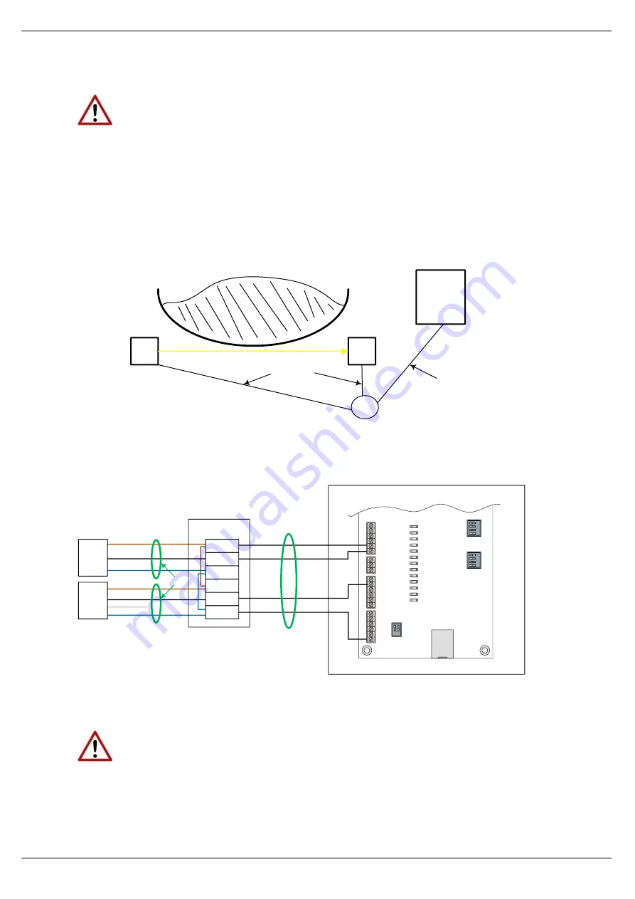
The two sensor enclosures can be wired to the Control Unit via a small junction box.
This box is typically installed underneath the conveyor belt and allows for improved
flexibility of mounting Control Unit as the distance is not limited by the sensor cable
length. Typical wiring details for this option are shown in figures below:
TX
RX
Control
Unit
CCG
Sensor
cabling
1 x 4C
Control Unit
Cable
Figure 2.7
–
Wiring of Sensors to Control Unit via Junction Box
+24VDC
Gate
0V
+24VDC
TX
RX
+24V
+24V
+0V
+0V
Gate
N/O Contact
N/C (not wired)
1
2
1
3
2
4
1
3
2
4
PWR
+24V
+24V
+24V
+24V
+24V
+24V
+24V
DO0
DO1
DO2
C34
DO3
DO4
DI0
DI1
DI2
DI3
COM
AI+
0V
DO0
DO1
DO2
DO3
DO4
DI0
DI1
M
O
D
E
S
Y
S
T
E
M
DI2
DI3
ETH
OK
STS
N/O
Contact
0V
Core 1
Core 2
Core 3
Core 4
JUNCTION BOX
CONTROL U NIT
Sensor cables
4 - Core Cable
Figure 2.8
–
Connection for Wiring of Sensors via Junction Box
NOTE: Ensure that the sensor units are connected with the correct
polarity. Incorrect polarity will damage the sensors.


