CIGWELD TRANSarc 130i Скачать руководство пользователя страница 78

TRANSARC 170i

KEY SPARE PARTS 

9-2 

Manual 0-5280

TRANSARC 170i POWER SOURCE SPARE PARTS

ITEM

PART NUMBER

DESCRIPTION

1

W7005800

PCB Power

2

W7005801

PCB Control

3

W7005803

PCB Front Panel (Display) 170i

4

W7005805

Knob Control

5

W7004909

Dinse Socket 50mm

2

6

W7005811

Control Socket 8 pin (Note that 8 pin control plug is part number 

UOA706900)

7

W7005812

Shielding Gas Outlet 5/8-18

8

W7005814

CT Output 

9

W7004908

Shielding Gas Solenoid Valve Assembly

10

W7005605

Shielding Gas Inlet Quick Connect

11

W7005813

Input Supply On/Off Switch

12

W7004913

Shielding Gas Hose Assembly (not supplied)

13

W7005806

Fan Assembly

14

W7003010

Input Rectifier (Shown mounted to PCB Power, item 1)

15

704461

Dinse Plug Male 50mm

(not shown)

Table 9-1

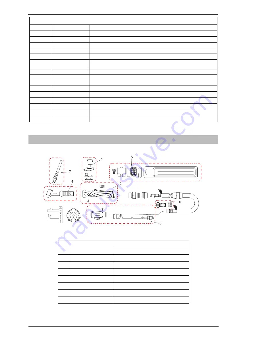
9.02  TIG Torch W4014604 (where supplied)

TIG Torch W4014604 spare parts diagram

A-11669

Figure 9-2

TIG TORCH SPARE PARTS

ITEM

PART NO.

DESCRIPTION

1

W7005900

Trigger assembly for 26F torch

2

W7005901

Handle assembly for 26F torch

3

W7005902

Dinse 50mm for 26F torch

4

W7005903

Flex head for 26F torch

5

BGSAK2

Tig accessory Kit

6

UOA706900

Cable Plug 8 pin

7

BG57Y02/R

Back Cap (Long)

Table 9-2

Содержание TRANSarc 130i

Страница 1: ...PFC A 11876 170i Service Manual Revision AA Issue Date February 27 2013 Manual No 0 5280 Operating Features TRANSarc welding Inverter...

Страница 2: ...you to avoid potential hazards that may exist when working with this product YOU ARE IN GOOD COMPANY The Brand of Choice for Contractors and Fabricators Worldwide CIGWELD is the Market Leading Brand...

Страница 3: ...LD Pty Ltd 71 Gower Street Preston Victoria Australia 3072 61 3 9474 7400 61 3 9474 7391 www cigweld com au Copyright 2013 by CIGWELD Pty Ltd All rights reserved Reproduction of this work in whole or...

Страница 4: ...netic Compatibility 3 4 SECTION 4 INSTALLATION OPERATION AND SETUP 4 1 4 01 Transarc 170i Power Source Controls Indicators and Features 4 1 3 07 Shielding Gas Regulator Operating Instructions where su...

Страница 5: ...6 7 08 Base Panel Removal 7 7 SECTION 8 ASSEMBLY PROCEDURES 8 1 8 01 Installing Base Panel 8 1 8 02 Installing Rear Panel 8 2 8 03 Installing Front Panel assembly 8 3 8 04 Installing Display PCB 8 4...

Страница 6: ......

Страница 7: ...ood electrical earth ground 11 Do not touch electrode while in contact with the work ground circuit 12 Use only well maintained equipment Repair or replace damaged parts at once 13 In confined spaces...

Страница 8: ...mate Range of Welding Current in Amps Minimum Shade Number of Filter s Manual Metal Arc Welding covered electrodes MMAW Less than or equal to 100 8 100 to 200 10 200 to 300 11 300 to 400 12 Greater th...

Страница 9: ...ourself and others from flying sparks and hot metal 2 Do not weld where flying sparks can strike flam mable material 3 Remove all flammables within 35 ft 10 7 m of the welding arc If this is not possi...

Страница 10: ...California Health Safety code Sec 25249 5 et seq NOTE Considerations About Welding And The Effects of Low Frequency Electric and Magnetic Fields The following is a quotation from the General Con clusi...

Страница 11: ...ompressed Gas Association 1235 Jefferson Davis Highway Suite 501 Arlington VA 22202 Code for Safety in Welding and Cutting CSA Standard W117 2 from Canadian Standards Association Stan dards Sales 178...

Страница 12: ...ns The product is designed and manufactured to a number of standards and technical requirements among them are IEC 60974 10 applicable to Industrial Equipment generic emissions and regulations AS 1674...

Страница 13: ...Direct Current DC Protective Earth Ground Line Line Connection Auxiliary Power Receptacle Rating Auxiliary Power Art A 04130_AB 115V 15A t t1 t2 X IPM MPM t V Fuse Wire Feed Function Wire Feed Towards...

Страница 14: ...GNIFICANT DC VOLTAGE exists after removal of input power on inverters Turn Off inverters disconnect input power and discharge input capacitors according to instruc tions in Troubleshooting Section bef...

Страница 15: ...tor and the device manufacturer WARNING OVERUSE can cause OVERHEATING Allow cooling period follow rated duty cycle Reduce current or reduce duty cycle before starting to weld again Do not block or fil...

Страница 16: ...nues to be examined Until the final conclusions of the research are reached you may wish to minimize your exposure to electromagnetic fields when welding or cutting To reduce magnetic fields in the wo...

Страница 17: ...shipping If there is any damage notify the carrier immediately to file a claim Furnish complete information concerning damage claims or shipping errors to the location in your area listed in the insi...

Страница 18: ...INTRODUCTION 2 2 Manual 0 5280 transarc 170i Notes...

Страница 19: ...arts To explain the 10 minute duty cycle period the following example is used Suppose a Welding Power Source is designed to operate at a 30 duty cycle 170 amperes at 26 8 volts This means that it has...

Страница 20: ...15 Amps Effective Input Current I1eff refer Note 2 13 Amps Maximum Input Current I1max 23 5 Amps Minimum Single Phase Generator Recommendation refer Note 4 6 6k W 8 5k VA at 0 8 PF STICK MMAW Welding...

Страница 21: ...Please refer to relevant local standards for further information prior to using in such areas A In locations in which freedom of movement is restricted so that the operator is forced to perform the w...

Страница 22: ...and filtering is provided in the Power Source 3 RadiationfromWeldingLeads Radiatedinterference from welding leads although pronounced in the vicinity of the leads diminishes rapidly with distance Keep...

Страница 23: ...onal precautions such as filtering of the mains supply Consideration should be given to shielding the supply cable of permanently installed welding equipment in metallic conduit or equivalent Shieldin...

Страница 24: ...ing the risk of injury to users or damage to other electrical equipment Where necessary the connection of the work piece to earth should be made by direct connection to the work piece but in some coun...

Страница 25: ...ight is off when the VRD is active Under this condition the open circuit voltage of the unit is limited to below 10V DC thus reducing the potential of serious electric shock such as when changing elec...

Страница 26: ...hich case actual welding amperage or voltage will be displayed or 3 a period of 10 seconds elapses following the completion of welding in which case the unit will return to preview mode The value disp...

Страница 27: ...arameter Control Panel Display Hot Start This parameter operates in STICK mode to improve the start characteristics for stick electrodes HOT START current is on top of the BASE current e g HOT START c...

Страница 28: ...or variability in joint fit up in certain situations with particular electrodes In general increasing the Arc Force control toward 100 maximum Arc Force allows greater penetration control to be achiev...

Страница 29: ...15 0 seconds Factory default is 1 0 second Base Current This parameter sets the TIG welding current Range is 5 to 170A Factory default is 120A Down Slope This parameter operates in TIG mode only and...

Страница 30: ...ally reduce oxidation of the tungsten electrode Range is 0 0 to 30 0 seconds Factory default is 5 0 seconds 5 Positive Welding Output Terminal The positive welding terminal is used to connect the weld...

Страница 31: ...Zero ohm minimum connection to 5k ohm remote control potentiometer 7 Wiper arm connection to 5k ohm remote control Amps GTAW TIG mode potentiometer 8 Not connected Table 4 1 8 Shielding Gas Outlet The...

Страница 32: ...ad Man Switch function greatly increases operator safety standard welding safety procedures should still be followed When the trigger is pressed the VRD voltage is activated and the user can start wel...

Страница 33: ...e 0V on the Power Source welding terminals and both VRD lights will be off In both 2T and 4T modes if the stick electrode is not touched to the work piece within three seconds the welding output will...

Страница 34: ...tor illuminate the output of the power source will be disabled Once the power source cools down this light will go OFF and the over temperature condition will automatically reset Note that the mains p...

Страница 35: ...as can dangerously propel a loose part 3 DO NOT remove the regulator from a cylinder without first closing the cylinder valve and releasing gas in the regulator high and low pressure chambers 4 DO NOT...

Страница 36: ...pen the cylinder valve If opened quickly a sudden pressure surge may damage internal regulator parts 2 With valves on downstream equipment closed adjust regulator to approximate working pressure It is...

Страница 37: ...heavy duty bayonet type terminals It is essential however that the male plug is inserted and turned securely to achieve a sound electrical connection D Connect the TIG torch trigger switch via the 8 p...

Страница 38: ...ION AND SETUP 3 14 Manual 0 5280 A 11666 Figure 4 7 Setup for TIG Welding 3 09 Foot Control Part No W4015800 Optional Accessory Art A 11338 Figure 4 8 Foot Control Art A 11339 1 2 3 4 5 6 7 8 Art A 11...

Страница 39: ...trol being connected although this can be adjusted while you are welding With the foot control connected the power source will only display minimum preview Amps until the foot control is depressed the...

Страница 40: ...minal If in doubt consult the electrode manufacturer Welding current flows from the power source via heavy duty bayonet type terminals It is essential however that the male plug is inserted and turned...

Страница 41: ...rmer than in a conventional power supply The AC is then rectified to extremely smooth DC The diagram to the below shows the basic electrical wiring of a DC output inverter power supply Inverter Techno...

Страница 42: ...Theory of Operation 5 2 Manual 0 5280 TRANSARC 170i Notes...

Страница 43: ...oltage in excess of 274VAC Connect Power Source to a supply voltage 274VAC 3 There is no weld output and the yellow over temperature light is on A Unit has overheated A Allow unit to cool with fan run...

Страница 44: ...Impurity in gas system causing solenoid to stay open or closed C Clean out gas system Disassemble solenoid clean out impurities D Faulty Power Inverter board D Replace Power Inverter board E Faulty Co...

Страница 45: ...Section 6 08 after removing case Before troubleshooting or applying power to unit complete the following checks to avoid causing further damage 6 04 Test Equipment and Tools Digital Multimeter DC clip...

Страница 46: ...nsure the mains supply plug is disconnected from receptacle Art A 11813 DC Bus Testing Multimeter Lead Placement Voltage with Supply voltage OFF Upper capacitor bank Positive meter lead to testpoint 1...

Страница 47: ...to testpoint 7 Negative meter lead to testpoint 8 0 2 0 8 VDC Table 6 3 IGBT s Multimeter set to measure Diode Voltage IGBT Testing Multimeter Lead Placement Ohms IGBT V8 V8 1 Positive meter lead to...

Страница 48: ...VDC Table 6 6 Diodes Multimeter set to measure Diode Voltage 6 08 Check main input rectifier Art A 11815 Input Rectifier Testing Multimeter Lead Placement Diode Voltage AC1 to DC Positive meter lead t...

Страница 49: ...tremely hazardous voltage and power levels present Do not touch any live parts Art A 11816 DC Bus Testing Multimeter Lead Placement Voltage with Supply voltage OFF Upper capacitor bank Positive meter...

Страница 50: ...p p square wave 15 VDC pk 4 IGBT 2 pwm drive signal 15V p p square wave 15 VDC pk 5 IGBT 1 pwm drive signal 15V p p square wave 15 VDC pk 6 Rectified secondary of current transformer TR8 15 VDC pk 7...

Страница 51: ...ignal 1 5V 5V 2 PFC OK signal 5V PFC OK Table 6 14 JC Header pin function connects to PFC header on control PCB HF 220V Header Pin Pin function signal 1 240VAC active 240VAC 2 240VAC active 0VAC Table...

Страница 52: ...5 VDC digital 4 Serial display eprom D OUT 5 VDC digital 5 DeadMan Switch 5V in Dead Man mode 5 VDC digital 6 Encoder Output A pulse output 5 VDC digital 7 Encoder Output D button 5 VDC digital 8 Enc...

Страница 53: ...in 5 4 Remote Amps Pot 8 pin socket pin 6 5 Trigger 8 pin socket pin 3 0 VDC Table 6 20 GUN Header pin function connects to GUNOUT header on Inverter PCB DY Header Pin Pin function signal 1 0 V 0 VDC...

Страница 54: ...Pin function signal 1 thermostat 2 thermostat Table 6 26 OT1 Header pin function connects to thermostats OT2 Header Pin Pin function signal 1 Link to 0V 2 0V 0VDC Table 6 27 OT2 Header pin function l...

Страница 55: ...OURCE Header pin function connects to DY2 header on inverter PCB 6 11 DIP switch settings Control and Display PCB s 1 DIP Switch SW1 control PCB Art A 11821 A 11847 SW1 position Function 1 Set to ON f...

Страница 56: ...DIP Switch S1 display PCB A 11889 SW1 position Function 1 Set to ON for Transarc 170i Mine Spec Plant W1007171 Power source W1007169 2 Set to OFF for Transarc 170i Non Mine Spec Plant W1007171 Power s...

Страница 57: ...s is 5A 0 5A Set front panel AMPS control to maximum Adjust Imax trimpot until output amps is 170A 1A Recheck settings Set front panel AMPS control to maximum Adjust A potentiometer so Amps display re...

Страница 58: ...Remove the load from the output terminals Set front panel AMPS control to maximum Connect a remote control device and set the remote control potentiometer to maximum Adjust the CAL REMOTE trimpot unti...

Страница 59: ...nd varying duty cycle The transformer return wire is taken from the terminal centre of the main DC bus capacitor bank the voltage at this point is approximately half the DC bus voltage Secondary outpu...

Страница 60: ...CONTROL BOARD WELDING TERMINALS SW1 C17 R56 C21 C19 T18 R101 103 C101 V8 COUT2 COUT1 L1 DISPLAY BOARD MB J12 SOLENOID 8 PIN REMOTE OT1 TH1 WV WELD POSITIVE WELD NEGATIVE CT1 INPUT RECTIFIER POSITIVE N...

Страница 61: ...information in Section 6 03 before proceeding Unplug unit before beginning Disassembly procedure 7 02 Case Removal Read and follow safety information in Section 6 03 before proceeding with disassembl...

Страница 62: ...harness from HF connector 5 Disconnect IFB harness from IFB connector 6 Disconnect DRIVE harness from DRIVE connector 7 Disconnect SOURCE harness from SOURCE connector 8 Disconnect WV harness from WV...

Страница 63: ...Section 6 03 before proceeding with disassembly 1 Unplug control wire 2 Dismantle two clips over the hose 3 Unscrew the nut Then the solenoid valve is disassembled 4 Disconnect the weld cable from the...

Страница 64: ...splay PCB Removal Read and follow safety information in Section 6 03 before proceeding with disassembly 1 Remove Display PCB Screws 2 Unscrew the set screw to remove the knob 3 Unplug the harness 4 Un...

Страница 65: ...nd follow safety information in Section 6 03 before proceeding with disassembly 1 Remove front panel screws 2 Remove Positive Output Terminal Bolt 3 Remove Negative Output Terminal Bolt 4 Disconnect h...

Страница 66: ...n in Section 6 03 before proceeding with disassembly 1 Remove 2 screws on rear panel 2 Remove On Off Switch wire 3 Remove gas hose from gas inlet 4 Remove ground screw 5 Remove fan screws to disassemb...

Страница 67: ...80 7 7 DISASSEMBLY PROCEDURE TRANSARC 170i 7 08 Base Panel Removal Read and follow safety information in Section 6 03 before proceeding with disassembly 1 Remove 4 screws to disassemble the base panel...

Страница 68: ...TRANSARC 170i DISASSEMBLY PROCEDURE 7 8 Manual 0 5280 Notes...

Страница 69: ...TRANSARC 170i Manual 0 5280 8 1 ASSEMBLY PROCEDURES 8 01 Installing Base Panel 1 Install base panel screws to assemble the base panel 1 A 11884 SECTION 8 ASSEMBLY PROCEDURES...

Страница 70: ...alling Rear Panel 1 Reinstall on off switch 2 Reinstall power cord 3 Reinstall fan install 4 screws 4 Reinstall ground wire 5 Reinstall gas hose to gas inlet 6 Reinstall input wire 7 Reinstall rear pa...

Страница 71: ...DURES 8 03 Installing Front Panel assembly 1 Reinstall Positive Output Terminals Bolt 2 Reinstall Negative Output Terminals 3 Reinstall gas hose to gas outlet 4 Reinstall 8 pin wire 5 Reinstall 2 scre...

Страница 72: ...stalling Display PCB 1 Plug the ribbon cable into the socket make sure it is correctly installed with the levers in the locked posi tion 2 Reinstall 4 screws to install display PCB 3 Reinstall set scr...

Страница 73: ...Output 1 Reinstall Current Transformer Output 2 Connect the control wire to Current Transformer Output 3 Connect the weld cable to the welding output terminal 4 Install the two clips over the gas hos...

Страница 74: ...to IFB connector 6 Plug DRIVE harness to DRIVE connector 7 Plug SOURCE harness to SOURCE connector 8 Plug WV harness to WV connector 9 Plug GUN harness to GUN connector 10 Plug DY harness to DY conne...

Страница 75: ...TRANSARC 170i Manual 0 5280 8 7 ASSEMBLY PROCEDURES 8 07 Installing Case 1 Install 12 screws to install the case 1 1 1 A 11878...

Страница 76: ...ASSEMBLY PROCEDURES 8 8 Manual 5280 TRANSARC 170i Notes...

Страница 77: ...TRANSARC 170i Manual 0 5280 9 1 KEY SPARE PARTS SECTION 9 KEY SPARE PARTS 9 01 Power Source A 11727 A 11728 Figure 9 1...

Страница 78: ...05 Shielding Gas Inlet Quick Connect 11 W7005813 Input Supply On Off Switch 12 W7004913 Shielding Gas Hose Assembly not supplied 13 W7005806 Fan Assembly 14 W7003010 Input Rectifier Shown mounted to P...

Страница 79: ...10 Figure 9 3 ELECTRODE HOLDER SPARE PARTS ITEM PART NO DESCRIPTION 1 W7006000 Rubber boot for electrode holder switch 2 W7006001 Push Button Switch for electrode holder 3 W7006002 Dinse 50mm for elec...

Страница 80: ...TRANSARC 170i KEY SPARE PARTS 9 4 Manual 0 5280 Notes...

Страница 81: ...R CONSEQUENTIAL DAMAGES SUCH AS BUT NOT LIMITED TO LOST PROFITS AND BUSINESS INTERRUPTION The remedies of the Purchaser set forth herein are exclusive and the liability of CIGWELD with respect to any...

Страница 82: ...our Accredited Distributor in writing of its claim within seven 7 days of becoming aware of the basis thereof and at its own expense returning the goods which are the subject of the claim to CIGWELD...

Страница 83: ...WARRANTY PERIOD PARTS LABOUR Original main power magnetics 3 Year 2 Year Original main power rectifiers printed circuit boards and power switch semiconductors 2 Year 2 Year All other circuits and com...

Страница 84: ...rn of goods to Cigweld or our Nominated Accredited Distributor Accredited Service Provider are the responsibility of the consumer This warranty is given Cigweld Pty Ltd A B N 56007226815 71 Gower Stre...

Страница 85: ...1257 224800 PT Victor Technologies Utama Indonesia Jl Angsana II Blok AE No 28 Delta Silicon I Cikarang Sukaresmi Bekasi 17550 Indonesia Tel 62 21 8990 6095 Fax 62 21 8990 6096 1867 http www Victortec...

Страница 86: ...Asia Pacific Regional Headquarters 71 Gower Street Preston Victoria Australia 3072 Telephone 61 3 9474 7400 FAX 61 3 9474 7391 Email enquiries cigweld com au www cigweld com au...

Отзывы: