


Example:
If the loop contains 2500L, comprising EG30%, for a unit with 6
Free Cooling coils, then it is necessary to add 30L (2500*1.2%)
of corrosion inhibitor every 8 years.
The corrosion inhibitors to be used are dipotassium hydrogen
phosphate type inhibitors. Only use products compatible with
aluminium. It is not recommended that the glycol is diluted to obtain
the desired concentration, so as to not reduce the original quantity
of corrosion inhibitors.
Formula equivalent to table 1 ► X = (V*P) / (1578*N)
-
X = Number of years between two corrosion inhibitor top-ups
-
V = Total volume in the loop (litres)
-
P = Glycol concentration (%)
-
N = Total number of Free Cooling coils connected to the water
loop
Formula equivalent to table 2 ► I = (V*P) / 2500
-
I = Volume of inhibitor to be added after X years (litres)
-
V = Total volume in the loop (litres)
-
P = Glycol concentration (%)
Protection against fouling:
The brine loop must be clean. To ensure the exchangers are able
to operate correctly, it is recommended that a sludge container,
settling container, or another filtration system is also installed
upstream of the unit, if necessary.
Frost protection
To prevent the risks of freezing when operating in low temperature
environments, the units equipped with the Free Cooling option
must be protected with a glycol-based solution, see Freezing curve
for Ethylene and Propylene glycol (section 12.2.1). The unit is
delivered without glycol. When filling with glycol, ensure that the
two motorised valves are open, along with the manual valve, to
guarantee that the glycol is correctly distributed within the unit.
If the customer loop requires testing or flushing, ensure that the
Free Cooling circuit valve is closed to prevent water from returning
to the Free Cooling micro-channel coils.
If water is introduced, drain the unit using the drain screws placed
on each coil and the drain taps at the low point in the Free Cooling
manifolds. Then add a glycol-based solution to protect the unit
from freezing.
NOTE: If the manufacturer's recommendations are not
respected, there is a risk of damage to the equipment.
The use of fresh water is prohibited with the Total and Partial
Free Cooling option.
Free cooling pipes
The maximum operating pressure for the total and partial Free
Cooling option is 6 bar. The nominal value is indicated on the unit's
name plate.
The manual valve installed on the unit's Free Cooling loop must
always be in the open position, except during draining or
maintenance.
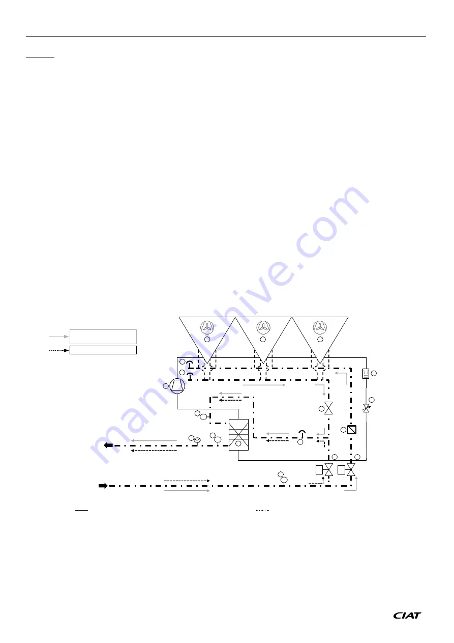
12.2.11.4 - Installation and hydraulic connection
Circulation diagram
T
T
2
4
5
7
7
9
8
7
9
T
10
6
M
6
11
1
M
9
3
3
3
- Free Cooling mode
- Combination mode
- Mechanical cooling mode
Refrigerant circuit:
Water circuit:
B
Evaporator
G
Motorised valve
C
Compressors
H
Temperature sensor
D
MCHE condenser & MCHE Free Cooling coil
I
Flow rate controller
E
Dehumidifier filter
J
Vent valve
F
Electronic expansion valve
K
Filter
L
Manual valve
12 - OPTIONS
AQUACIAT
POWER
™ LD/ILD
EN-82


