M Series User Manual
B-1
020-100009-05 Rev. 1 (09-2010)
Appendix B: GPIO
This section explains how to use a GPIO link from the projector to external equipment, such as devices for
3D synchronizing.
B.1
GPIO Port
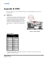
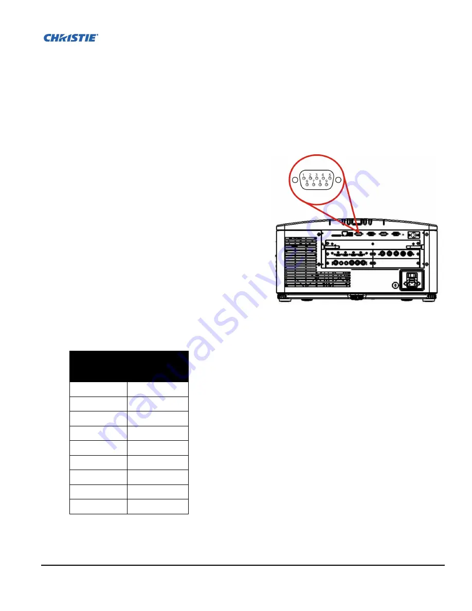
The GPIO connector located on the input panel provides
a flexible method of interfacing a wide range of external
I/O devices to the projector. There are 7 GPIO pins
available on the 9pin D-Sub GPIO connector, which are
configurable via RS-232 commands. See
Figure B-1 -
GPIO Connector
. The other two pins are reserved for
ground and power - see table below for pin identifica-
tion.
Table B.1 GPIO Pin
The serial cable required for connecting the external device to the projector’s GPIO connector, must be
compatible with the external device.
GPIO PINS
PIN #
SIGNAL
Pin 1
+ 12V (200mA)
Pin 2
GPIO 2
Pin 3
GPIO 4
Pin 4
GPIO 6
Pin 5
Ground
Pin 6
GPIO 1
Pin 7
GPIO 3
Pin 8
GPIO 5
Pin 9
GPIO 7
F
IGURE
B-1 - GPIO C
ONNECTOR
Содержание M Series
Страница 1: ...M Series U S E R M A N U A L 020 100009 05 ...
Страница 2: ......
Страница 3: ...M Series U S E R M A N U A L 020 100009 05 ...
Страница 14: ......
Страница 46: ......
Страница 120: ......
Страница 131: ...Section 6 Troubleshooting M Series User Manual 6 7 020 100009 05 Rev 1 09 2010 FIGURE 6 1 ...
Страница 132: ......
Страница 147: ...M Series User Manual A 1 020 100009 05 Rev 1 09 2010 Appendix A Menu Tree A 1 M Series Menu Tree ...
Страница 148: ......
Страница 152: ......
Страница 167: ......


