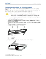
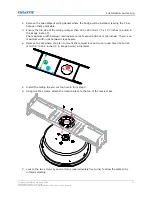


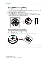


7. To adjust the orientation within 90°, loosen the three M3 screws (A in the image in step 6).
When the two Δ marks (C in the image in step 6) are aligned, the X axis of the receiver box
orients along the main beam of the grid.
8. Hang the support clip on the main beam.
9. Confirm the location.
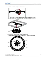
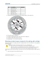
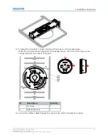
10. Install two self-drilling screws (A in the image below) from the side through the 4.5 mm (0.18
inches) diameter hole.
ID
Description
Quantity
A
Self-drilling screw (ST4.2 X
1’)
2
B
Support clip
1
C
Load wire
1
D
Load wire holes
2
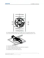
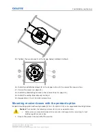
11. Add the load wire (C and D in the image step 10) to connect the support clip to the load
bearing surface (higher than the tile) according to local building regulations.
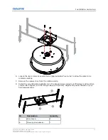
12. Connect safety cables between the M5 nuts on the top of the receiver box and the holes on the
bottom bracket (A in the image in step 13).
13. Align the holes on the bottom bracket with the holes on the support clip and insert the four M4
tamper-proof screws (B in the image below) leaving them loosely fastened.
Installation and setup
CounterAct Installation and Setup Guide
38
020-103456-01 Rev. 1 (09-2021)
Copyright
©
2021 Christie Digital Systems USA, Inc. All rights reserved.
Содержание 174-005106-XX
Страница 1: ...Installation and Setup Guide 020 103456 01 CounterAct ...
Страница 49: ......


